Supercharge Your Innovation With Domain-Expert AI Agents!

Smoke extraction and dust removal system for electric furnace

A dust removal system, electric furnace technology, applied in the direction of furnace, furnace components, waste heat treatment, etc., can solve the problems of high dust concentration at the outlet, low dust removal efficiency, high dust content, etc.

Pending Publication Date: 2022-03-01
四川都钢钢铁集团股份有限公司
View PDF0 Cites 0 Cited by
  • Summary
  • Abstract
  • Description
  • Claims
  • Application Information

AI Technical Summary

Problems solved by technology

The existing flue gas dedusting devices basically use direct spraying dedusting devices, the dust removal effect is not good, and there is no flue gas dehydration function
[0003] In addition, the traditional wet flue gas desulfurization system will have a series of problems such as scaling, suspended solid blockage, ionic liquid failure, corrosion, and insufficient desalination capacity. One of the important factors causing the above problems is the large amount of dust contained in the sintering flue gas into the desulfurization system
Although the flue gas goes through the double dedusting function of electric dust removal and scrubber before entering the desulfurization system, the dust removal efficiency of the electric dust collector and the existing scrubber is low, so that the dust content entering the desulfurization system is still high, resulting in A series of problems occurred in the operation
[0004] The internal structure of the existing scrubber tower is mainly a single spray tower or packed tower. Due to the short gas-liquid contact time, small contact area, and uneven airflow distribution in the tower, the scrubber with a single structure has low dust removal efficiency. Low, high dust concentration at the outlet

Method used


Image

  • Smoke extraction and dust removal system for electric furnace
  • Smoke extraction and dust removal system for electric furnace

Examples


Embodiment Construction

[0017] In order to make the purpose, technical solutions and advantages of the embodiments of the present invention clearer, the technical solutions in the embodiments of the present invention will be clearly and completely described below in conjunction with the accompanying drawings in the embodiments of the present invention. Obviously, the described embodiments It is some embodiments of the present invention, but not all of them. The components of the embodiments of the invention generally described and illustrated in the figures herein may be arranged and designed in a variety of different configurations.

[0018] Accordingly, the following detailed description of the embodiments of the invention provided in the accompanying drawings is not intended to limit the scope of the claimed invention, but merely represents selected embodiments of the invention. Based on the implementation manners in the present invention, all other implementation manners obtained by persons of or...


PUM


Abstract

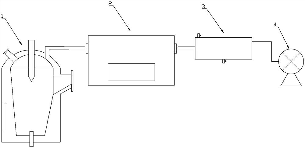
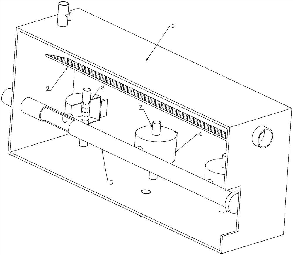
The invention relates to the technical field of flue gas dust removal, and discloses an electric furnace flue gas suction and dust removal system which comprises an electric melting furnace, a settling chamber, a dust removal chamber and an exhaust fan, the electric melting furnace is communicated with the settling chamber through a flue gas outlet pipe, the settling chamber is communicated with the dust removal chamber through a waste gas pipe, and an exhaust port is formed in the dust removal chamber and connected with the exhaust fan through a pipeline. A main gas pipe is arranged in the dust removal chamber, one end of the main gas pipe is closed, the other end of the main gas pipe is connected with the smoke outlet pipe, a branch pipe is arranged on the main gas pipe, a fairing is arranged on the branch pipe, a lifting pipe is arranged on the fairing, and a through hole is formed in the lifting pipe located in the fairing. The dust removal device has the beneficial effects that negative pressure is generated in the dust removal chamber through the exhaust fan, dust removal water in the dust removal chamber is pressed into the water lifting pipe, meanwhile, flue gas in the electric melting furnace enters the water lifting pipe through the fairing, gas-water mixing is formed and sprayed out of the water lifting pipe, and dust in the flue gas is fused into the dust removal water and falls back to the bottom of the dust removal chamber; waste gas is discharged out of the dust chamber through the exhaust port, and dust removal is thorough.

Description

technical field [0001] The invention relates to the technical field of smoke and dust removal, in particular to an electric furnace smoke extraction and dust removal system. Background technique [0002] The iron and steel industry is one of the industries that cause serious air pollution, and the sintering process is the main source of pollution in the iron and steel industry. In recent years, more and more sinter plants have installed flue gas desulfurization systems to reduce SO emissions 2 , part of which uses the organic amine wet desulfurization process. After the dust contained in the flue gas enters the desulfurization system, it will have a great impact on the desulfurization efficiency and stable operation of the desulfurization system, so it is particularly important to improve the dust removal efficiency in the pretreatment section. The existing flue gas dedusting devices basically adopt direct spraying dedusting devices, the dedusting effect is not good, and t...

Claims


Application Information

Patent Timeline
Patent Type & Authority Applications(China)
IPC IPC(8): F27D17/00B01D47/06B01D50/40
CPCF27D17/001F27D17/002F27D17/008B01D47/063Y02P10/25
Inventor 邓彪陈建康曾利平傅有全
Owner 四川都钢钢铁集团股份有限公司
Features
  • R&D
  • Intellectual Property
  • Life Sciences
  • Materials
  • Tech Scout
  • Unparalleled Data Quality
  • Higher Quality Content
  • 60% Fewer Hallucinations
Learn More