
Optical imaging system and method

An optical imaging system and optical imaging technology, applied in the direction of optics, optical components, and optical devices, can solve the problems of unclear image details, achieve high resolution, improve collection efficiency, and expand the field of view

Pending Publication Date: 2022-03-01
HEBEI UNIV OF ENG
View PDF10 Cites 1 Cited by
  • Summary
  • Abstract
  • Description
  • Claims
  • Application Information

AI Technical Summary

Problems solved by technology

[0002] Ordinary optical microscopes are mainly obtained through lens groups. Such microscopes are usually only suitable for real-time observation. After observation, the details of the image will soon be unclear

Method used


Image

  • Optical imaging system and method
  • Optical imaging system and method
  • Optical imaging system and method

Examples


Embodiment Construction

[0025] 1. The optical imaging system of the present invention.

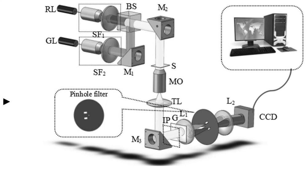
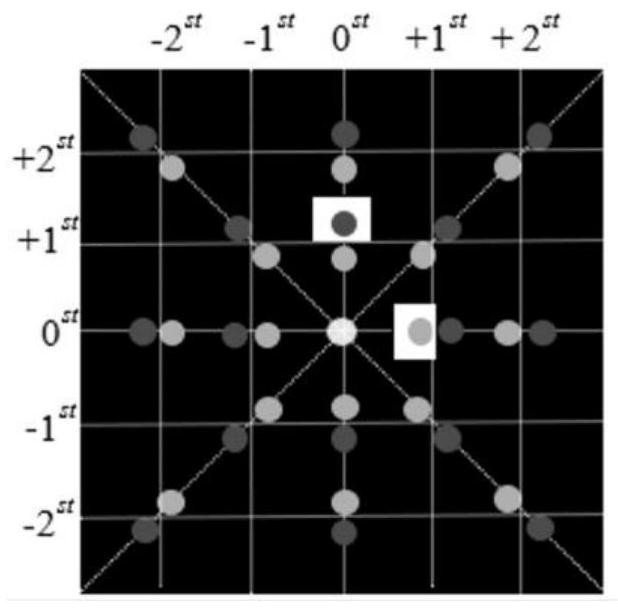
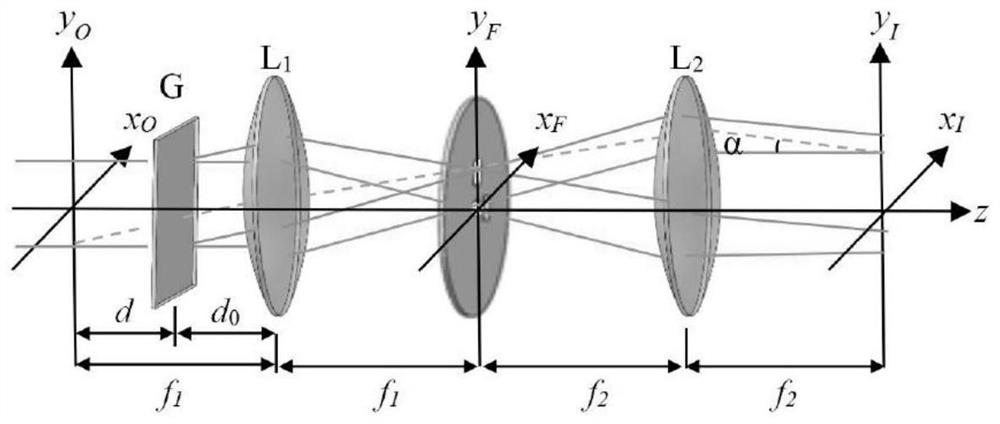
[0026] Such as figure 1 As shown, it is the optical system of the present invention, including the first laser RL, the second laser GL, the first beam expander collimator SF 1 , the second beam expander collimator SF 2 , mirror M 1 , M 2 , M 3 , beam combiner BS, sample S, microscope objective MO, collimator lens TL, two-dimensional grating G, first lens L 1 , the second lens L 2 And filter, CCD. The first laser RL adopts He-Ne laser (λ 1 =632.8nm), the second laser GL adopts semiconductor laser (λ 2 = 532nm). The light emitted by the first laser passes through the first beam expander collimator SF 1 Obtain the first light beam, and the light emitted by the second laser passes through the second beam expander collimator SF 2 The second beam is obtained, and the two beams are combined by the beam combiner BS to irradiate the sample at the same time, then enlarged by the microscope objective MO, collimat...


PUM

PropertyMeasurementUnit
diameteraaaaaaaaaa
refractive indexaaaaaaaaaa

Abstract

The invention relates to an optical imaging system and method. Two laser beams with different wavelengths are utilized to irradiate a measured object, so that phase information of the measured object is carried, parallel light is formed after the laser beams are amplified and collimated through a microscope objective, diffracted light with different levels is obtained through a two-dimensional grating, direct current items in 0-level diffracted light and + 1-level diffracted light are made to pass through a 4f imaging system and a filter in a combined mode, and therefore the phase information of the measured object is obtained. The other levels of diffraction light are filtered out, so that two orthogonal interference fringe images are formed, the two orthogonal interference fringe images are collected by a CCD (Charge Coupled Device), and a three-dimensional image of the measured object is reconstructed through a computer program.

Description

technical field [0001] The application relates to an optical imaging system and method, belonging to the field of optical imaging. Background technique [0002] Ordinary optical microscopes are mainly obtained through lens groups. Such microscopes are usually only suitable for real-time observation, and the details of the image are quickly lost after observation. With the continuous development of semiconductor technology and laser technology, a digital holographic microscope has appeared at this stage, which can obtain the phase image of the imaging object while obtaining the intensity image of the imaging object, or it can obtain the three-dimensional image of the imaging object , and can permanently save the obtained 3D image. [0003] The above-mentioned digital holographic microscope technology uses CCD to collect the hologram of the imaging object, input the hologram into the computer, and use the algorithm to simulate the actual hologram reproduction process in the c...

Claims


Application Information

Patent Timeline
Patent Type & Authority Applications(China)
IPC IPC(8): G01B11/24G02B27/10G02B27/42G02B27/44G03H1/12
CPCG01B11/24G01B11/2441G02B27/1006G02B27/4238G02B27/44G03H1/12
Inventor 王华英王杰宇江夏男
Owner HEBEI UNIV OF ENG
Learn More