
Wireless fee control water meter based on Internet of Things

An Internet of Things, water meter technology, applied in wireless architecture, transmission of electricity meter data, telemetry/remote control selection devices, etc., can solve the problem of poor antifreeze effect of water meters, and achieve the effect of improving antifreeze effect, uniform temperature and increasing heat.

Inactive Publication Date: 2022-03-01
王依明
View PDF0 Cites 0 Cited by
  • Summary
  • Abstract
  • Description
  • Claims
  • Application Information

AI Technical Summary

Problems solved by technology

[0004] Based on the technical problem of poor antifreeze effect of existing water meters, the present invention proposes an Internet of Things wireless fee-controlled water meter

Method used


Image

  • Wireless fee control water meter based on Internet of Things
  • Wireless fee control water meter based on Internet of Things
  • Wireless fee control water meter based on Internet of Things

Examples


Embodiment 1

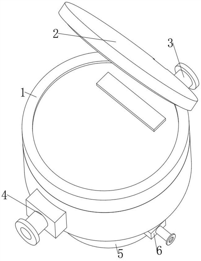
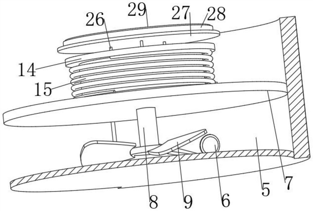
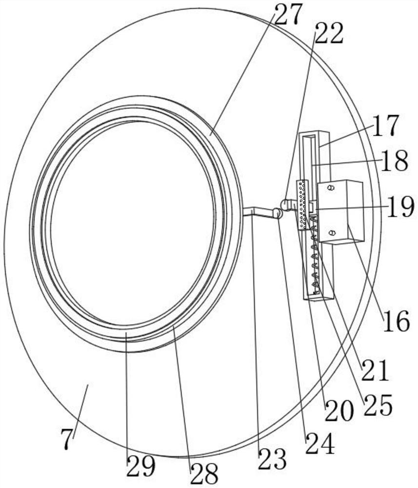
[0029] refer to Figure 1-4 , an Internet of things wireless fee control water meter, including a water meter body 1, a case 5 fixed to the bottom of the water meter body 1 by bolts, a partition 7 fixed in the case 5 by bolts, and a connector 6 fixed on one side of the case 5 , the connecting head 6 is set under the partition 7, the partition 7 is provided with a connecting shaft 8, the connecting shaft 8 and the partition 7 are connected by bearing rotation, the bottom of the connecting shaft 8 is fixed with an impeller 9 by bolts, and the connecting shaft 8 The top is sleeved and fixed with a first collar 10, and the outer wall of the first collar 10 is fixed with a plurality of struts 11 distributed in an annular array by bolts, and the outer sides of the plurality of struts 11 are fixed with the same second collar 12 by bolts , the outer wall of the second collar 12 is bonded with a ring magnet 13, the top of the separator 7 is fixed with a bobbin 14 by bolts, the ring mag...

Embodiment 2

[0036] refer to Figure 1-7 , an Internet of Things wireless fee-controlled water meter, the top of the second collar 12 is fixed with a plurality of electric push rods 26 distributed in a circular array by bolts, and the output shafts of the multiple electric push rods 26 are connected to the same supporting plate 27, and the supporting plate 27 The top is fixed with a first ring plate 28 by bolts, the top of the first ring plate 28 is provided with a second ring plate 29 , and an adjustment mechanism is arranged between the second ring plate 29 and the first ring plate 28 .

[0037] Further, the adjustment mechanism includes a plurality of second springs 31 distributed in an annular array. The top of the first ring plate 28 is provided with a ring groove 30. The second spring 31 is fixed to the bottom inner wall of the ring groove 30 by bolts. The second spring 31 and the second The ring plates 29 are fixed by bolts. The inner wall of the ring groove 30 is provided with a pl...


PUM


Abstract

The invention belongs to the technical field of water meters, and particularly relates to an internet-of-things wireless fee control water meter which comprises a water meter body, a housing is fixed to the bottom of the water meter body, a partition plate is fixed in the housing, a connector is fixed to one side of the housing in a penetrating mode, a connecting shaft is arranged on the partition plate in a penetrating mode, an impeller is fixed to the bottom of the connecting shaft, and a first lantern ring is fixed to the top of the connecting shaft in a sleeving mode. A plurality of supporting rods are fixed to the circumferential outer wall of the first lantern ring, a second lantern ring is fixed to the outer sides of the supporting rods, an annular magnet is bonded to the circumferential outer wall of the second lantern ring, a winding reel is fixed to the top of the partition plate, a coil is wound around the winding reel, and a storage battery is fixed to one side of the top of the partition plate. According to the anti-freezing water meter, the connector is communicated with the main pipeline through the water pipe, the water meter body is installed on the branch pipeline where the water meter body is located, when a user of any branch pipeline sharing the same main pipeline uses water, water in the main pipeline can flow, then water in the housing is triggered to flow, electric energy is formed, heat dissipation is conducted, and therefore the anti-freezing effect is achieved.

Description

technical field [0001] The invention relates to the technical field of water meters, in particular to an Internet of Things wireless fee-controlled water meter. Background technique [0002] Water meters are instruments for measuring water flow. Most of them measure the cumulative flow of water. They are generally divided into two types: volumetric water meters and speed water meters. Then choose the water meter of the specification with the usual flow rate closest to this value as the first choice. The working principle of the water meter is that the water flow tangentially impacts the impeller from the water inlet of the watch case to make it rotate, and then continuously records the number of revolutions of the impeller through the gear reduction mechanism, so that Record the cumulative flow through the water meter. [0003] The water meter is installed on the branch pipes leading to different users, so that the water volume can be measured for different users independen...

Claims


Application Information

Patent Timeline
Patent Type & Authority Applications(China)
IPC IPC(8): G01F15/00G01F15/10G01F15/14G07F9/10G07F15/00H04Q9/00
CPCG01F15/00G01F15/14G01F15/10G07F15/00G07F9/105H04Q9/00H04Q2209/40H04Q2209/60
Inventor 王依明
Owner 王依明
Learn More