Finite element topological structure construction method for improving calculation application efficiency of overhead line system

A topology and construction method technology, applied in special data processing applications, design optimization/simulation, instruments, etc., can solve problems such as the lack of systematic topology construction methods, achieve high computing application efficiency, reduce the error rate, application wide range of effects

Active Publication Date: 2022-03-01
CHINA RAILWAY ELECTRIFICATION SURVEY DESIGN & RES INST
View PDF6 Cites 0 Cited by
  • Summary
  • Abstract
  • Description
  • Claims
  • Application Information

AI Technical Summary

Problems solved by technology

[0003] The core of the application of the finite element method is not only the construction of the differential element type, but also the digital construction of the actual engineering model. In the article "Three-dimensional Calculation of the Length of the Catenary Suspension Chord in the Whole Anchor Section", there is a corresponding single-bearing cable single-contact line However, in the subway, urban rail, light rail transit system and GB / T 32591-2016 "Validation of Dynamic Interaction Simulation of Pantograph and Catenary in Rail Transit Current Collection System", the actual line The composition of the catenary is rich and varied, and the original single catenary and single catenary cable cannot meet the needs of existing computing applications, and there is no effective systematic topology construction method

Method used


Image

  • Finite element topological structure construction method for improving calculation application efficiency of overhead line system
  • Finite element topological structure construction method for improving calculation application efficiency of overhead line system
  • Finite element topological structure construction method for improving calculation application efficiency of overhead line system

Examples


Embodiment 1

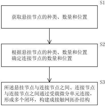
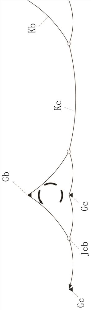
[0024] Embodiments of the present invention provide a method for constructing a finite element topology structure that improves the efficiency of catenary calculation and application, and constructs a topology structure for a simple suspended catenary, such as figure 1 and figure 2 As shown, it includes the following steps:

[0025] S1: Obtain the type, quantity and location of the suspension nodes; the above data is based on the actual situation of the project. For the catenary with simple suspension, the suspension nodes include the contact wire suspension node Gc and the sling suspension node Gb.

[0026] S2: Determine the number and location of connecting nodes according to the type, quantity and location of hanging nodes. The number and location of connecting nodes are based on the spacing of the same type of suspension nodes, which can be found in the design manual. Said connecting nodes comprise contact line-cable connection nodes Jcb, which are arranged on the cont...

Embodiment 2

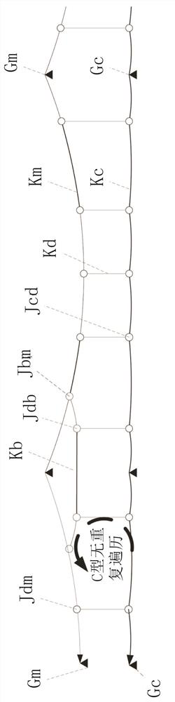
[0030] Embodiments of the present invention provide a method for constructing a finite element topology structure that improves the efficiency of catenary calculation and application, and constructs a topology structure for a chain-type suspended catenary, such as figure 1 and image 3 As shown, it includes the following steps:

[0031] S1: Obtain the type, quantity and location of the suspension nodes; the above data is based on the actual situation of the project. For catenary suspended by chain, the suspension nodes include contact wire suspension nodes Gc and catenary cable suspension nodes Gm.

[0032] S2: According to the type, quantity and location of the suspension nodes and the design manual, determine the number and location of the connection nodes from bottom to top, that is, first determine the number and location of the connection nodes on the contact line, and then determine the number and location of the connection nodes on the catenary cable The number and lo...

Embodiment 3

[0038] Embodiments of the present invention provide a method for constructing a finite element topology structure that improves the efficiency of catenary calculation and application. It is aimed at constructing a topology structure for a Japanese-style double-chain suspension catenary, such as figure 1 and Figure 4 shown, which includes the following steps:

[0039] S1: Obtain the type, quantity and location of the suspension nodes; the above data is based on the actual situation of the project. In the catenary with Japanese-style double-chain suspension, the suspension nodes include contact wire suspension nodes Gc, catenary cable suspension nodes Gm, and sling suspension nodes Gb.

[0040] S2: According to the type, quantity and location of the suspension nodes and the design manual, determine the number and location of the connection nodes from bottom to top; Location.

[0041] The connecting nodes include contact line-hanging string connecting node Jcd, hanging string...


PUM


Abstract

The invention provides a finite element topological structure construction method for improving the calculation application efficiency of a contact network. The finite element topological structure construction method comprises the following steps that S1, the types, the number and the positions of suspension nodes are obtained; s2, determining the number and the positions of connecting nodes according to the types, the number and the positions of the suspension nodes; and S3, the suspension nodes and the connection nodes are connected through the loaded differential units, the connection nodes are connected through the loaded differential units, a plurality of closed loops are formed, and the overhead line system topological structure is constructed. The application range of the method is expanded from single-contact-line and single-carrier-cable chain type suspension to single-contact-line simple suspension, double-carrier-cable and double-contact-line chain type suspension, complex chain type suspension and other complex and changeable structures, the workload of field personnel is reduced, the error occurrence rate is greatly reduced, and calculation and application time consumption is obviously reduced; and meanwhile, the adaptability to the working condition of mixed suspension of the overhead line system is more excellent, and the pre-configuration calculation is more accurate in a topological structure closer to reality.

Description

technical field [0001] The invention belongs to the application field of finite element calculation of rail transit catenary, and in particular relates to a method for constructing a finite element topology structure for improving the efficiency of catenary calculation and application. Background technique [0002] Based on the increasingly in-depth research on catenary calculation using the finite element method, the construction and operation and maintenance intensity in the field of rail transit has gradually decreased, and the efficiency has gradually increased. The development has shifted to the direction of independent construction of finite element calculation applications. Therefore, more detailed and systematic requirements are put forward for the engineering application of finite element method. [0003] The core of the application of the finite element method is not only the construction of the differential element type, but also the digital construction of the ac...

Claims


Application Information

Patent Timeline
Patent Type & Authority Applications(China)
IPC IPC(8): G06F30/18G06F30/23G06F119/14
CPCG06F30/18G06F30/23G06F2119/14
Inventor 皋金龙李逢源陈凯周玉杰周玉伟李汉卿杨建兴陈敏王正朱政唐浩
Owner CHINA RAILWAY ELECTRIFICATION SURVEY DESIGN & RES INST
Why Eureka
Try Eureka