Supercharge Your Innovation With Domain-Expert AI Agents!

Signal receiving device

A signal receiving device and a technology for outputting signals, applied in the direction of DC-coupled DC amplifiers, differential amplifiers, etc., can solve the problems of signal distortion, the duty cycle of the output signal of the differential amplifier cannot be maintained in the correct range, etc., to maintain the correctness Effect

Pending Publication Date: 2022-03-01
WINBOND ELECTRONICS CORP
View PDF0 Cites 0 Cited by
  • Summary
  • Abstract
  • Description
  • Claims
  • Application Information

AI Technical Summary

Problems solved by technology

Such a change may make the duty cycle of the output signal generated by the differential amplifier unable to maintain in the correct range, causing distortion of the received signal

Method used


Image

  • Signal receiving device
  • Signal receiving device
  • Signal receiving device

Examples


Embodiment Construction

[0041] Reference will now be made in detail to the exemplary embodiments of the present invention, examples of which are illustrated in the accompanying drawings. Wherever possible, the same reference numbers will be used in the drawings and description to refer to the same or like parts.

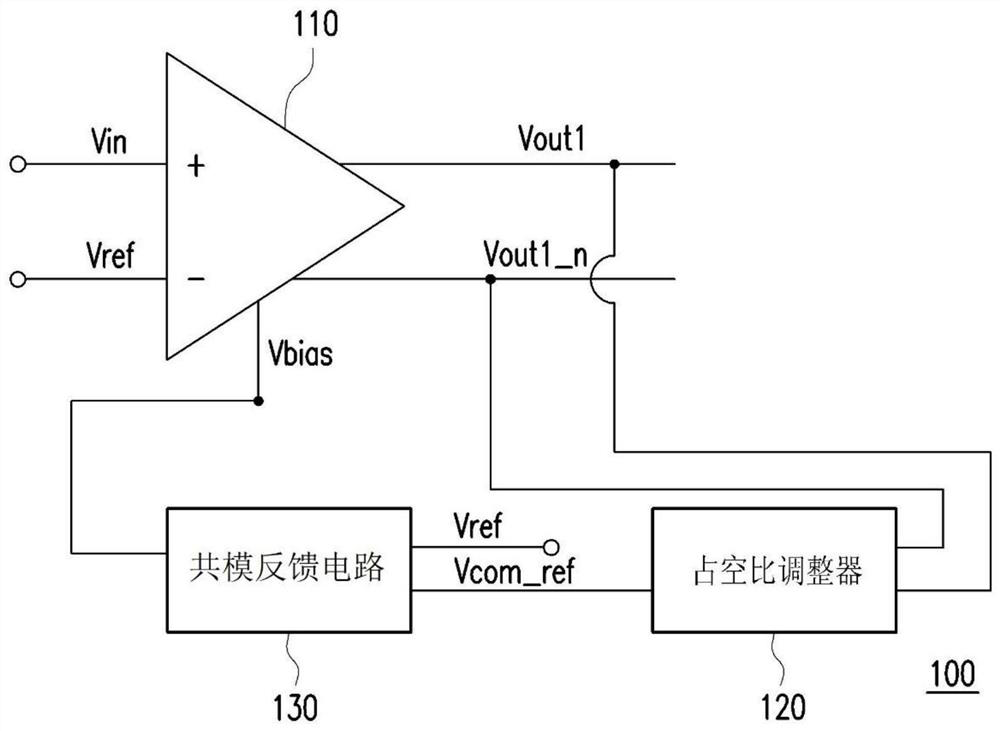
[0042] figure 1 A schematic diagram of a signal receiving device according to an embodiment of the present invention is shown. The signal receiving device 100 includes an amplifier 110 , a duty ratio regulator 120 and a common-mode feedback circuit 130 . The amplifier 110 receives an input signal Vin, a reference voltage Vref and a bias voltage Vbias. The amplifier 110 generates the common current according to the bias voltage Vbias, and based on the common current, generates the complementary output signal Vout1 and the output signal Vout1_n according to the comparison input signal Vin and the reference voltage Vref. Wherein, the amplifier 110 may be a differential amplifier circuit. T...


PUM


Abstract

The invention provides a signal receiving device. The signal receiving device comprises a first amplifier, a duty ratio adjuster and a common mode feedback circuit. The first amplifier receives an input signal, a reference voltage and a bias voltage. The first amplifier generates a first common current according to a bias voltage, and generates a first output signal and a second output signal which are complementary according to a comparison input signal and a reference voltage based on the first common current. The duty ratio adjuster performs charging and discharging actions on the selected capacitor according to the first output signal or the second output signal so as to generate a detection voltage, and generates a common reference voltage according to the detection voltage. The common mode feedback circuit generates a bias voltage by comparing the common reference voltage and the reference voltage so as to compensate for distortion of the first amplifier caused by the change of the transconductance value.

Description

technical field [0001] The invention relates to a signal receiving device, in particular to a signal receiving device capable of adjusting the duty cycle of an output signal. Background technique [0002] In the prior art, the pre-amplifier in the signal receiver is usually implemented by a differential amplifier. Wherein, the differential amplifier operates based on a common current, and the voltage value of the output signal can be determined according to the magnitude of the current flowing through the differential transistor. [0003] In the prior art, based on the fact that the common current is fixed, when the turn-on voltage of the differential transistor varies due to process drift or environmental factors, the transconductance value of the differential transistor will change accordingly. Such a change may make the duty cycle of the output signal generated by the differential amplifier unable to maintain in the correct range, causing the received signal to be distor...

Claims


Application Information

Patent Timeline
IPC IPC(8): H03F3/45
CPCH03F3/45
Inventor 吴镇宇陈君政
Owner WINBOND ELECTRONICS CORP
Features
  • R&D
  • Intellectual Property
  • Life Sciences
  • Materials
  • Tech Scout
  • Unparalleled Data Quality
  • Higher Quality Content
  • 60% Fewer Hallucinations
Learn More