Current multiplexing low-power-consumption differential super-regeneration radio frequency front-end circuit

A technology of current multiplexing and RF front-end, which is applied in the direction of electrical components, transmission systems, etc., can solve the problems of power supply common-mode noise suppression decline, etc., achieve good power supply rejection ratio, suppress common-mode noise, and solve the problem of poor common-mode rejection ratio Effect

Pending Publication Date: 2022-03-01
SOUTHEAST UNIV +1
View PDF4 Cites 0 Cited by
  • Summary
  • Abstract
  • Description
  • Claims
  • Application Information

AI Technical Summary

Problems solved by technology

[0006] Purpose of the invention: Aiming at the above-mentioned prior art, a current-multiplexing low-power differential super-regenerative RF front-end circuit is proposed to solve

Method used


Image

  • Current multiplexing low-power-consumption differential super-regeneration radio frequency front-end circuit
  • Current multiplexing low-power-consumption differential super-regeneration radio frequency front-end circuit
  • Current multiplexing low-power-consumption differential super-regeneration radio frequency front-end circuit

Examples


Embodiment Construction

[0015] The present invention will be further explained below in conjunction with the accompanying drawings.

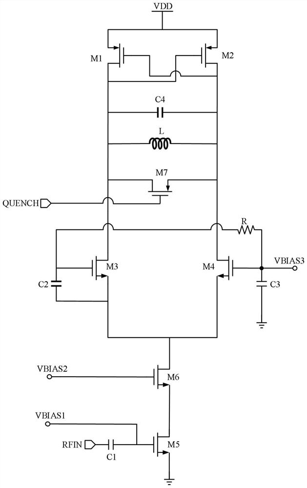
[0016] A current multiplexing low-power differential super-regenerative radio frequency front-end circuit includes an LC regenerative oscillator circuit and a low-noise amplifying circuit. like image 3 As shown, the LC regenerative oscillator circuit includes a PMOS transistor M1, a PMOS transistor M2, a PMOS transistor M7, an NMOS transistor M3, an NMOS transistor M4, capacitors C2-C4, an inductor L and a resistor R. The source terminals of the PMOS transistor M1 and the PMOS transistor M2 are connected to the DC voltage VDD, and the gate terminals are respectively connected to the drain terminals of the other side to form a cross-coupling state to provide negative resistance. The drain terminals of the PMOS transistor M1 and the PMOS transistor M2 are connected to the drain terminals of the NMOS transistor M3 and the NMOS transistor M4 respectively, and the source ...


PUM


Abstract

The invention discloses a current multiplexing low-power-consumption differential super-regeneration radio frequency front-end circuit which is of a vertically stacked structure formed by an LC regenerative oscillation circuit and a low-noise amplification circuit, and the low-noise amplification circuit is of a cascode amplifier structure. The LC regenerative oscillation circuit serves as a load circuit of the low-noise amplification circuit, the low-noise amplification circuit serves as a tail current bias of the LC regenerative oscillation circuit, and the LC regenerative oscillation circuit and the low-noise amplification circuit multiplex direct current. A differential short-circuit capacitance technology is introduced into a traditional current multiplexing super-regeneration radio frequency front-end circuit to convert a single-end signal output by a low-noise amplification circuit into a differential signal and inject the differential signal into a differential LC regeneration oscillation circuit, Balun is effectively saved, common-mode noise on a power supply can be well suppressed, a good power supply rejection ratio is achieved, and the power supply rejection ratio is improved. The problem that the common-mode rejection ratio is poor due to the fact that a traditional current multiplexing super-regeneration radio frequency front end adopts a single-end structure is solved.

Description

technical field [0001] The invention relates to a differential super-regenerative radio frequency front-end circuit. Background technique [0002] The super-regenerative receiver was invented by Armstrong in 1922. Because of its simple structure and low cost, it is widely used in some simple wireless communication devices. [0003] A typical super-regenerative receiver is mainly composed of a receiving antenna, a low-noise amplifier, a super-regenerative oscillator, an envelope detection circuit, a low-pass filter, an amplifying circuit and an extinguishing signal generating circuit, such as Figure 4 shown. The RF front-end of the super-regenerative receiver consists of a low-noise amplifier and a super-regenerative oscillator. Among them, the super regenerative oscillator is actually an oscillator working in the intermittent oscillation state, and the intermittent frequency is determined by the extinguishing signal. When no RF signal is received, the oscillator has a lo...

Claims


Application Information

Patent Timeline
IPC IPC(8): H04B1/40
CPCH04B1/40Y02D30/70
Inventor 徐建石永柳王鑫
Owner SOUTHEAST UNIV
Why Eureka
Try Eureka