

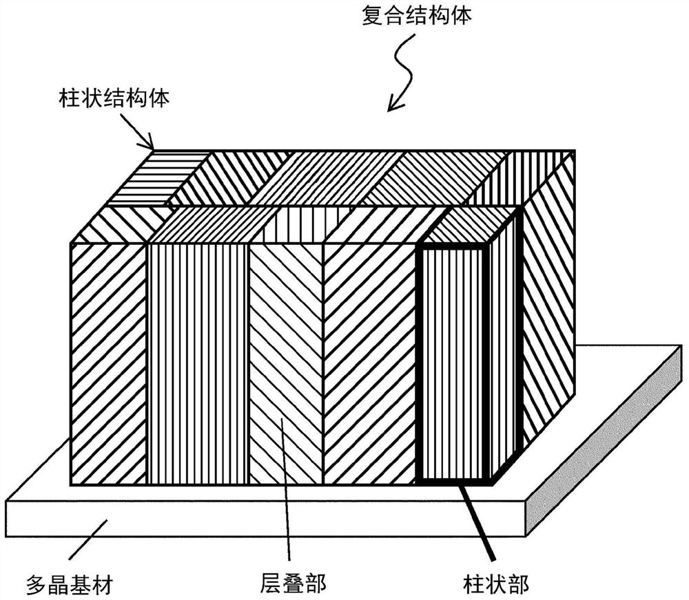
Electrode having column structure having laminated portion
A technology for structures and laminations, applied to structural parts, battery electrodes, circuits, etc., can solve problems such as reduced mechanical strength, and achieve long-term performance, catalyst activity, and high mechanical strength.
- Summary
- Abstract
- Description
- Claims
- Application Information
AI Technical Summary
Problems solved by technology
Method used
Image

Examples
Embodiment 1
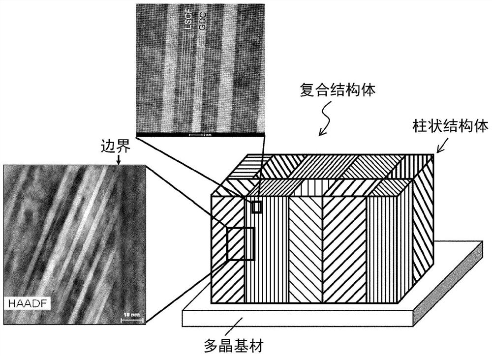
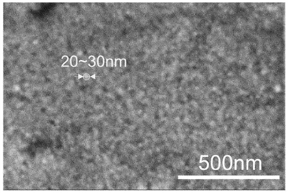
[0036] Using a PLD device (PVD Products, NanoPLD), in polycrystalline (Ce, Gd)O 2 (Ce,Gd)O on the substrate 2 (Hereafter, sometimes "(Ce, Gd)O 2 "Denoted as "GDC") and (La, Sr)(Co, Fe)O 3 (Hereafter, sometimes "(La, Sr) (Co, Fe) O 3 "Denoted as "LSCF") by simultaneous film formation to produce a composite structure. It should be noted that at an oxygen partial pressure of 35mTorr, a substrate temperature of 750°C, a film formation time of 100 minutes, a distance between the target and the substrate of 75mm, and a substrate rotation speed of 10rpm , Laser (Coherent, Compex Pro 102F, KrF wavelength 248nm) incident angle 60 °, laser energy 200mJ, laser frequency 10Hz under the conditions of film formation. The TEM image of the composite structure of the present embodiment and HAADF- STEM images are shown in figure 2 , the surface SEM images are shown in image 3 .
[0037] exist figure 2 Shown in is the cross-sectional TEM image (scale bar: 2 nm) of the upper rectangular...
Embodiment 2
[0041] Same as Example 1, in polycrystalline (Ce, Gd)O 2 The GDC and LSCF were simultaneously deposited on the substrate to form a columnar structure on the substrate. In addition, under the conditions of an oxygen partial pressure of 100 mTorr, a film formation time of 90 minutes, a laser energy of 275 mJ, and a laser frequency of 20 Hz, without heating the substrate, a current collector layer of a porous layer of LSCF was formed on the columnar structure by the PLD method, so that Electrodes were fabricated on polycrystalline GDC substrates. The cross-sectional SEM image of the electrode of this embodiment is shown in Figure 5 .
[0042] Such as Figure 5 As shown, an electrode having a columnar structure composed of LSCF and GDC ("LSCF-GDC" in the figure) and an LSCF nano-collector layer composed of nano-sized columnar particles of LSCF was obtained. Such as Figure 5 As shown, in the columnar structure of this example, columnar portions having a width of 20 nm to 30 ...
Embodiment 3
[0044] Same as in Example 1, GDC and (La, Sr) CoO on the polycrystalline GDC substrate 3 (Hereafter, sometimes "(La, Sr) CoO 3 "Denoted as "LSC") to form a columnar structure on the substrate. In addition, under the conditions of oxygen partial pressure of 100mTorr, film formation time of 45 minutes, laser energy of 275mJ, and laser frequency of 20Hz, the substrate was not heated. , use the PLD method to form the collector layer of the porous layer of LSC on the columnar structure to manufacture the electrode member. The columnar structure and the collector layer are also formed on the back of the substrate in the same way to be used as an electrode performance test. Symmetrical battery.
[0045] Using the battery of Example 3, the electrode reaction resistance (ASR) of the electrode and the ohmic resistance of the battery were calculated by the following method. First, LSC paste was coated on the current collector layer of the battery of Example 3, and a gold mesh was press...
PUM
| Property | Measurement | Unit |
|---|---|---|
| width | aaaaa | aaaaa |
| thickness | aaaaa | aaaaa |
| thickness | aaaaa | aaaaa |
Abstract
Description
Claims
Application Information