Automatic small hardware cutting machine and cutting method thereof

A cutting machine and small hardware technology, applied in metal processing, metal processing equipment, feeding devices, etc., can solve the problems of low yield rate of hardware parts, so as to enhance market competitiveness, improve product yield and efficiency, and save personnel cost effect

Pending Publication Date: 2022-03-04
河源市皓吉达通讯器材有限公司
View PDF0 Cites 0 Cited by
  • Summary
  • Abstract
  • Description
  • Claims
  • Application Information

AI Technical Summary

Problems solved by technology

[0004] The purpose of the present invention is to solve the problem of low yield rate in the existing hardware, and propose a small hardware automatic cutting machine and its cutting method

Method used


Image

  • Automatic small hardware cutting machine and cutting method thereof

Examples


Embodiment 1

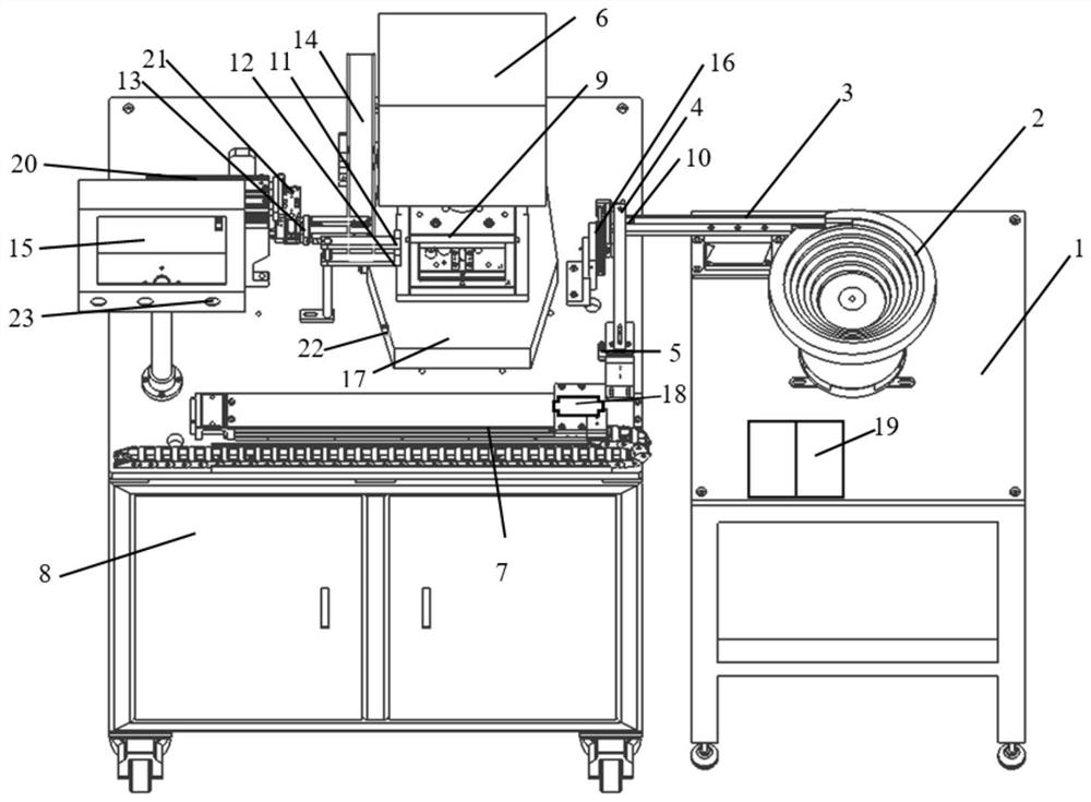
[0027] Example 1 figure 1 It is given, a small hardware automatic cutting machine, including a table 1, and a first controller 19 on one side on the table, and a vibration plate 2 is provided on the other side, the vibrating plate 2 includes a straight feeder, a linear feeder The middle is equipped with a first inductor 3. The end of the line feeder is connected to the automatic pusher 16. The vibrating plate 2 can vibrate feed, and send the product to be cut to the automatic pusher 16 through the line feeder to automatically push The material 16 is adjacent to the first suction nozzle 4 of the first cylinder 5, and the other end of the first cylinder 5 is connected to the servo module 7, and the servo module 7 is provided with a distribution box 8, and the servo module 7 is fixedly installed. On one side of the assembler 8, a fixing frame 17 is attached to one side of the distribution box 8, and a press mold 9 is provided. The upper end of the stamping die 9 is connected by a fix...

Embodiment 2

[0028] In an embodiment, the line feeder is provided with a fourth sensor 10, and the fourth sensor 10 is adjacent to the automatic pusher 16, and the product reaches the end of the line feeder, fourth The inductor 10 senses a product, transmitting information to the automatic pusher 16, and the automatic pusher 16 will push the product to the designated position, and the vibrating plate 2 realizes the automatic feeding of the product.

Embodiment 3

[0029] In the case of the first example, the servo module 7 is provided with a vacuum generator 18, the first cylinder 5, the second cylinder 13, the third cylinder 20, and the fourth cylinder 21, which are occurring by vacuum. Generate generated.


PUM


Abstract

The invention discloses a small hardware automatic cutting machine and a cutting method thereof, and relates to the technical field of hardware automatic side cutting, the small hardware automatic cutting machine comprises a workbench, a vibration disc is arranged on the workbench, the vibration disc comprises a linear feeder, a first sensor is arranged in the middle of the linear feeder, an automatic pusher is connected to the tail end of the linear feeder, and a second sensor is arranged in the middle of the automatic pusher. The automatic pusher is adjacent to a first air cylinder, the first air cylinder is connected with a servo module, the bottom of the servo module is connected with a distribution box, one side of the upper end of the distribution box is connected with a fixing frame, a stamping die is arranged on the fixing frame, the upper end of the stamping die is connected with a motor, and a second air cylinder is installed on the side edge of the stamping die. A piston rod on the second air cylinder is connected with a second suction nozzle, and a discharging groove is formed in the lower edge of the piston rod connected with the second air cylinder. Automatic feeding and receiving are carried out through the servo module and the air cylinder, the production efficiency and the qualified rate of products are improved, and the personnel cost is saved.

Description

Technical field [0001] The present invention relates to the field of hardware automatic side cutting technology, and more particularly to a small hardware automatic cutting machine and a cutting method thereof. Background technique [0002] Due to the current requirements of the mobile phone, the height size of the OIS coil is reduced, and the coil is required to be sized, and the product solder is low, the bracket and motor shell are used to adsorb the adsorption and hot melt adhesive method. Low adhesion, linear loops and thermal deformation caused by insufficient unplugging force, resulting in technical defects such as coil size accuracy, lack of flatness. [0003] To this end, we propose a small hardware automatic cutting machine to solve the above problems. Inventive content [0004] It is an object of the present invention to solve the problem of low-quality problems in existing hardware, and the proposed small hardware automatic cutting machine and its croping method. [...

Claims


Application Information

Patent Timeline
Patent Type & Authority Applications(China)
IPC IPC(8): B21D28/34B21C51/00B21D28/24B21D43/00B21D43/02B21D43/18B21D45/00B21D45/02
CPCB21D28/34B21D28/24B21D43/003B21D43/02B21D43/18B21D45/003B21D45/02B21C51/00
Inventor 金腾芳
Owner 河源市皓吉达通讯器材有限公司
Why Eureka
Try Eureka