Multi-channel heat storage device and using method thereof

A heat storage device, multi-channel technology, applied in heat storage equipment, heat exchange equipment, heat exchanger types, etc., can solve problems such as pollution, and achieve the effects of avoiding mutual pollution, increasing heat recovery efficiency, and increasing heat storage capacity.

Pending Publication Date: 2022-03-04
思安新能源股份有限公司
View PDF0 Cites 0 Cited by
  • Summary
  • Abstract
  • Description
  • Claims
  • Application Information

AI Technical Summary

Problems solved by technology

[0004] The purpose of the present invention is to provide a multi-channel heat storage device and its use method to solve the problem that various heat exchange media are on the same heat exchange surface in the existing heat storage device and cause pollution

Method used


Image

  • Multi-channel heat storage device and using method thereof
  • Multi-channel heat storage device and using method thereof
  • Multi-channel heat storage device and using method thereof

Examples


Embodiment

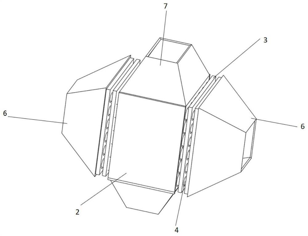
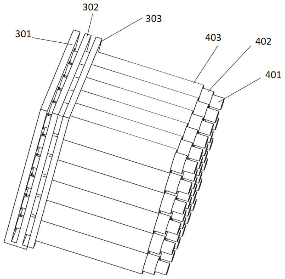
[0042] Let the first heat exchange medium flow into the first heat exchange medium circulation channel 9 inside the inner pipe body 401 through the through hole on the third orifice plate 301, and the inner pipe body 401 exchanges heat with the heat exchange medium, and then the first The other end of the heat exchange medium circulation passage 9 is discharged.

[0043] And / or, make the second heat exchange medium enter into the second heat exchange medium circulation path 10 along the through hole 1 between the third orifice plate 301 and the second orifice plate 302, and then pass through the second orifice plate The through hole on the 302 flows into the gap between the middle pipe body 402 and the inner pipe body 401; the middle pipe body 402 and the inner pipe body 401 exchange heat with the second heat exchange medium, and then from the other end of the second heat exchange medium circulation passage 10 discharge.

[0044] And / or, make the third heat exchange medium en...


PUM


Abstract

The invention discloses a multi-channel heat storage device and a using method thereof.The multi-channel heat storage device comprises at least one heat storage assembly, each heat storage assembly comprises an inner side pipe body, a middle pipe body and an outer side pipe body which are coaxially sleeved from inside to outside, and the length of the middle pipe body is smaller than that of the inner side pipe body and larger than that of the outer side pipe body; the limiting assembly comprises six flat plates uniformly provided with a plurality of through holes, and the flat plates are divided into two first pore plates, two second pore plates and two third pore plates according to different diameters of the through holes; the diameters of the two first pore plates, the two second pore plates and the two third pore plates are R4, R5 and R6 respectively; the two ends of the inner side pipe body, the two ends of the middle pipe body and the two ends of the outer side pipe body are sleeved with the two third pore plates, the two second pore plates and the two first pore plates respectively. The problem that pollution is caused due to the fact that various heat exchange media in an existing heat storage device are located on the same heat exchange face is solved.

Description

technical field [0001] The invention belongs to the field of energy recovery, and in particular relates to a multi-channel heat storage device and an application method thereof. Background technique [0002] Flue gas is the main way for general energy-consuming equipment to waste energy. For example, the energy consumption of boiler smoke exhaust is about 15%, while other equipment such as printing and dyeing industry's setting machines, dryers and kilns mainly consume energy through flue gas discharge. . In order to achieve the purpose of saving energy and reducing consumption, recovering the waste heat of flue gas is also an important way to save energy. [0003] Most of the solid heat storage equipment used in the existing flue gas recovery process is a single-channel pipe body with a heat storage unit, that is, the exothermic gas and the heat-absorbing gas flow in the same channel, because they both flush the same heat exchanger. The hot side, so when a gas has low cle...

Claims


Application Information

Patent Timeline
Patent Type & Authority Applications(China)
IPC IPC(8): F28D20/00F28F9/22
CPCF28D20/00F28F9/22Y02E60/14
Inventor 范培源王成徐吉富魏立婷陈久林
Owner 思安新能源股份有限公司
Why Eureka
Try Eureka