Reactor core melt cooling and collecting device

A core melt and collection device technology, which is applied in the field of core trapping, can solve the problems of limited cooling capacity, easy leakage, and large occupied volume, and achieves the effects of improving cooling capacity, high safety and reliability, and less space occupied by the structure

Active Publication Date: 2022-03-04
NUCLEAR POWER INSTITUTE OF CHINA
View PDF4 Cites 0 Cited by
  • Summary
  • Abstract
  • Description
  • Claims
  • Application Information

AI Technical Summary

Problems solved by technology

[0004] The technical problem to be solved by the present invention is: there are still many disadvantages in the existing core catcher, the cooling device and the collection device are set independently, the cooling capacity is limited, the occupied volume is relatively large, and the core melt is separated between the cooling device and the collection device. Migration between them is easy to leak, resulting in the release of radioactive substances to the environment. The purpose of the present invention is to provide a cooling and collecting device for core molten matter, based on structural improvements, to solve the above technical problems, thereby reducing the meltdown of the reactor pit and the risk of radioactive substances. Unleashing risk to improve safety in the event of a reactor accident

Method used


Image

  • Reactor core melt cooling and collecting device
  • Reactor core melt cooling and collecting device
  • Reactor core melt cooling and collecting device

Examples


Embodiment 1

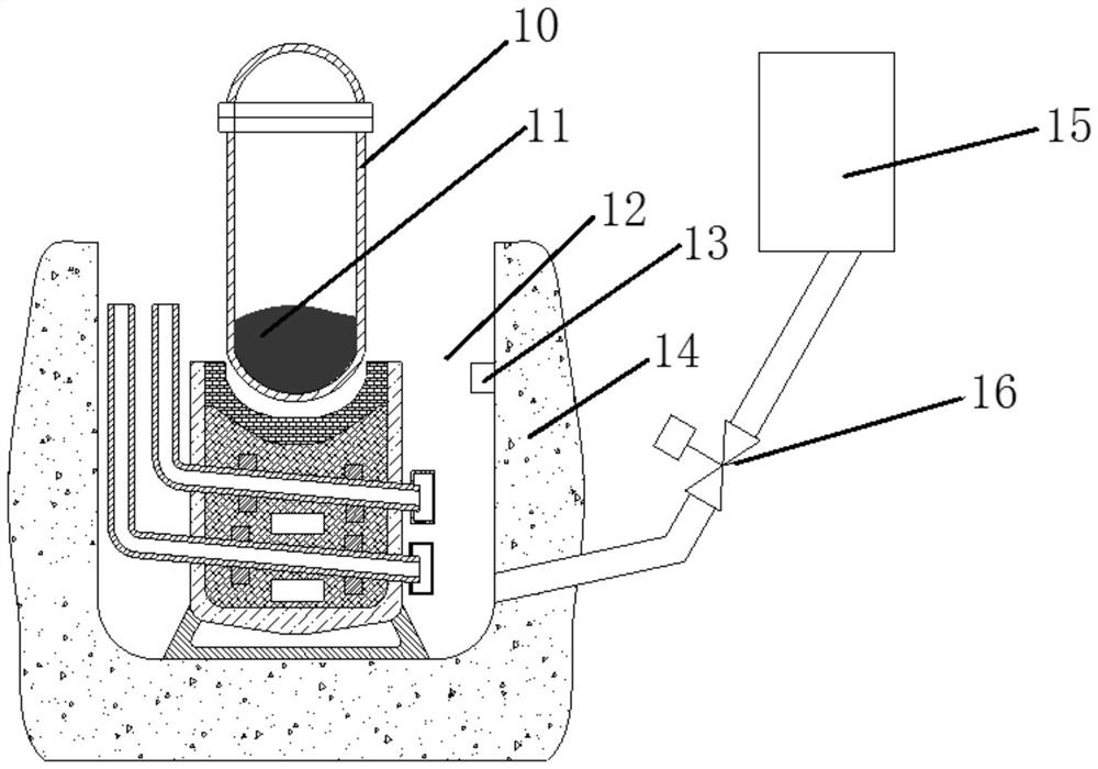
[0046] This embodiment provides a core melt cooling collection device, such as figure 1 As shown, it includes a steel collection container and a stack cavity 14, the steel collection container is arranged in the stack cavity 14 for collecting core melt, and the gap between the steel collection container and the stack cavity 14 forms a cooling cavity 12. The cooling cavity 12 is used to cool the core melt collected in the steel collection vessel.

[0047] The mouth of the reactor cavity is higher than the steel collection vessel, and the area of ​​the mouth of the reactor cavity is larger than that of the steel collection vessel, so as to prevent the core melt from migrating out of the steel collection vessel.

Embodiment 2

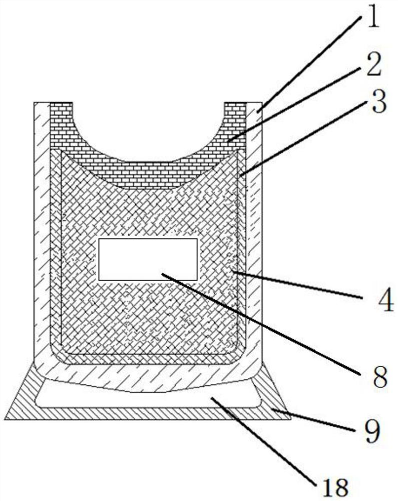
[0049] The difference between this embodiment and the previous embodiment lies in, as Figure 2-Figure 4 As shown, the steel collection container includes: thermal shock protection layer 2, container protection layer 3 and steel container 1;

[0050] Both the container protection layer 3 and the thermal shock protection layer 2 are arranged in the steel container 1, the container protection layer 3 is close to the circumferential inner wall and the bottom inner wall of the steel container 1, and the thermal shock protection layer 2 is arranged in the container protection Above the layer 3, the thermal shock protection layer 2 and the container protection layer 3 form a closed chamber A17, and the top of the thermal shock protection layer 2 is flush with the steel container 1.

[0051] The bottom of the thermal shock protection layer 2 is depressed towards the bottom of the steel container 1 , and the side wall of the shock protection layer 2 is close to the circumferential inn...

Embodiment 3

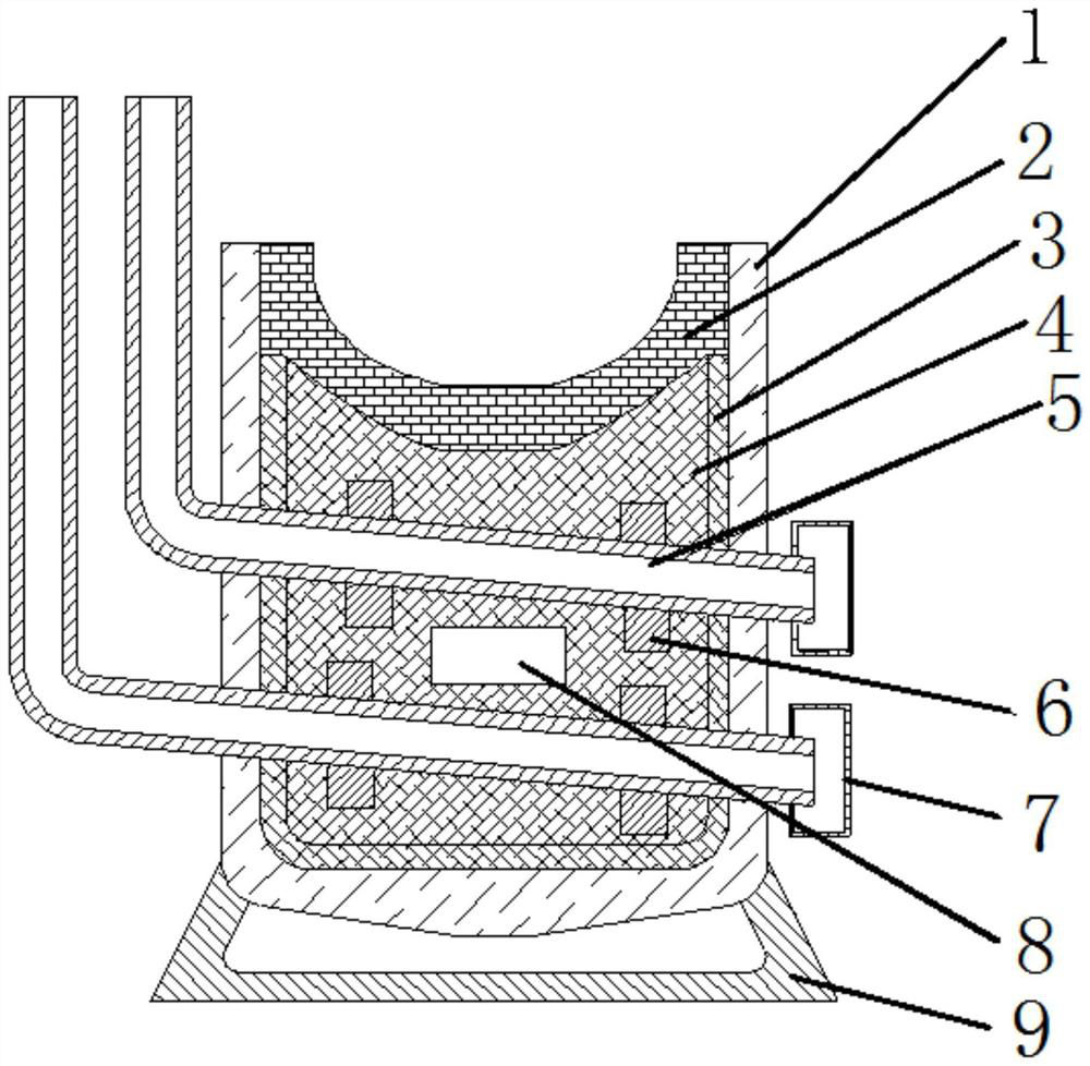
[0054] The difference between this embodiment and the previous embodiment is that it also includes a heat transfer tube 5, a plurality of heat transfer tubes run through the side wall of the steel container 1 and the closed chamber A17, and the heat transfer tubes 5 run through the side wall of the steel container 1 After that, it extends upward along the axis of the steel container, and the extended part of the heat transfer tube is higher than the steel container 1. A filter 7 is installed at the entrance of the heat transfer tube 5, and the height of the heat transfer tube 5 penetrating into the steel container 1 is low. The height at which the heat transfer tube 5 passes out of the steel container 1.

[0055] It also includes a protective wall 4 for the heat transfer tube, and multiple protective walls are installed in parallel in the airtight chamber A, and the protective wall 4 is in contact with the thermal shock protection layer 3;

[0056] A plurality of heat transfer...


PUM


Abstract

The invention discloses a reactor core melt cooling and collecting device which is characterized in that a cooling cavity is formed by a gap between a steel collecting container and a reactor cavity, the steel collecting container is used for expanding, collecting and cooling a reactor core melt layer by layer at the same time, and then the reactor core melt is further cooled in the cooling cavity, so that the cooling capacity of the whole device is improved; and the reactor core melt and the cooling device are of an integrated structure, the structure of the formed cooling cavity occupies less space, when a serious accident of the reactor occurs, the reactor core melt can be quickly and efficiently collected, the melt can be cooled in a passive manner, the melt is solidified in a collection container, the release of radioactive substances is reduced, and the reactor is safe, reliable and higher in efficiency.

Description

technical field [0001] The invention relates to the technical field of core capture, in particular to a core melt cooling and collecting device. Background technique [0002] Under severe accident conditions in the reactor, materials such as fuel elements, control rods and stainless steel supports in the pressure vessel will melt to form a complex mixture, collectively known as the core melt. The temperature of the liquid core melt is as high as 3000°C. After melting through the pressure vessel, it will migrate to the reactor cavity. The melt would interact with the water in the reactor cavity, causing a steam explosion that would destroy the structural integrity of the reactor cavity. After the high-temperature molten material comes into contact with the concrete, it will ablate the concrete, and under long-term action, it will melt the bottom plate of the reactor cavity, destroy the integrity of the containment vessel, and cause the release of radioactive substances to th...

Claims


Application Information

Patent Timeline
IPC IPC(8): G21C9/016G21C15/18
CPCG21C9/016G21C15/18Y02E30/30
Inventor 宫厚军李朋洲黎阳昝元锋杨祖毛卓文彬许建辉
Owner NUCLEAR POWER INSTITUTE OF CHINA
Why Eureka
Try Eureka