Fuel cell humidifying system and fuel cell system

A fuel cell and control system technology, applied in the direction of fuel cells, fuel cell additives, fuel cell control, etc., can solve the problems of high cost, complex structure, stack flooding, etc., and achieve high spray atomization quality and simple processing technology , cheap effect

Pending Publication Date: 2022-03-04
浙江锋源氢能科技有限公司
View PDF12 Cites 0 Cited by
  • Summary
  • Abstract
  • Description
  • Claims
  • Application Information

AI Technical Summary

Problems solved by technology

This method of humidification can reduce the weight and volume of the proton exchange membrane battery; however, this method of humidification is difficult to control the humidity of the reaction gas. decline
External humidification is to configure a humidification system outside the proton exchange membrane fuel cell to humidify the reactant gas before entering the fuel cell; at present, there are many ways to use external humidification, for example, ultrasonic atomization humidification, hollow fiber Humidification method, drum type humidification method, etc.; however, these devices are often complex in structure, high in cost, low in humidification efficiency and cannot be adjusted in time

Method used


Image

  • Fuel cell humidifying system and fuel cell system
  • Fuel cell humidifying system and fuel cell system
  • Fuel cell humidifying system and fuel cell system

Examples


Embodiment 1

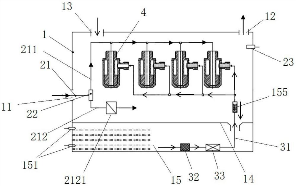
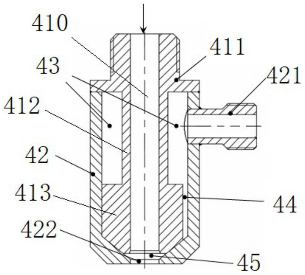
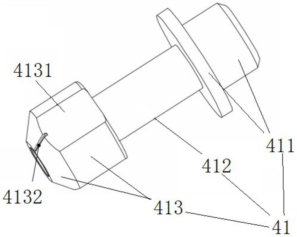
[0043] On the one hand, if figure 1 As shown, this embodiment provides a fuel cell humidification system, wherein the fuel cell humidification system includes: a tank 1 , a dual-fluid injector 4 , and a compressed gas pipeline. Wherein, the dual-fluid injector 4 is installed in the box body 1; and the dual-fluid injector 4 has an air inlet and a water inlet; wherein, the dual-fluid injector 4 is used for mixing the incoming water and the incoming air and injecting it into the casing 1 Inside. The compressed gas pipeline includes an air intake pipe 21, a first branch pipe 212, and a second branch pipe 211; wherein, the air intake pipe 21 is installed at the compressed gas inlet 11 of the casing 1; 212 communicates with the second branch pipe 211 ; wherein, the first branch pipe 212 is used to transport the compressed gas into the tank 1 ; the second branch pipe 211 communicates with the air inlet of the dual-fluid injector 4 . Wherein, the first branch pipe 212 or the second ...

Embodiment 2

[0048] Preferably, this embodiment provides a fuel cell humidification system, compared with the previous embodiment, such as figure 1 As shown, the present embodiment is further designed as follows:

[0049] A humidity sensor 23 is installed in the box body 1 for real-time detection of the humidity of the compressed gas in the box body 1; wherein the humidity sensor 23 is used for connecting the control system to feed back the real-time humidity detection value of the compressed gas in the box body 1 to Control system; the control system issues instructions according to the real-time humidity detection value, controls the gas flow regulating device 2121, and adjusts the compressed gas flow flowing from the intake pipe 21 to the first branch pipe 212 and the second branch pipe 211.

[0050] Preferably, the control system is a fuel cell ECU.

[0051] Specifically, when the real-time humidity detection value of the compressed gas in the box 1 is lower than the set requirement, ...

Embodiment 3

[0057] Preferably, this embodiment provides a fuel cell humidification system, compared with the above embodiments, such as figure 1 As shown, the present embodiment is further designed as follows:

[0058] A water storage space 15 is provided in the box body 1 of this embodiment; wherein, the water inlet of the dual-fluid injector 4 communicates with the water storage space 15 through a water inlet pipeline 31; a water injection port 13 is also provided on the box body 1 to pass through The water injection port 13 injects water into the water storage space 15 .

[0059] Preferably, a partition 14 is arranged inside the tank 1 ; wherein, the partition 14 divides the tank 1 into an upper space and a lower space; wherein, the lower space is a water storage space 15 . Wherein, the dual-fluid injector 4 and the compressed gas pipeline are located in the upper space of the box body 1; wherein, a water inlet hole is opened on the partition plate 14; preferably, the water injection ...


PUM


Abstract

The invention relates to a fuel cell humidifying system and a fuel cell system. The fuel cell humidifying system comprises a box body, a double-fluid ejector and a compressed gas pipeline, the double-fluid ejector is mounted in the box body; the double-fluid ejector is provided with an air inlet and a water inlet; the double-fluid ejector is used for mixing inlet water and inlet air and then ejecting the mixed water and inlet air into the box body; the compressed gas pipeline comprises a gas inlet pipe, a first branch pipe and a second branch pipe; the air inlet pipe is respectively communicated with the first branch pipe and the second branch pipe through a tee joint; the first branch pipe is used for directly conveying compressed gas into the box body; and the second branch pipe is communicated with an air inlet of the double-fluid ejector. A gas flow adjusting device is arranged on the first branch pipe or the second branch pipe, and the flow of the compressed gas flowing from the gas inlet pipe to the first branch pipe and the second branch pipe is adjusted by controlling the gas flow adjusting device, so that the humidity of the compressed gas in the box body is adjusted. According to the invention, the humidity of the reaction gas can be adjusted in time through a simple structure.

Description

technical field [0001] The invention relates to the technical field of fuel cells, in particular to a fuel cell humidification system and a fuel cell system. Background technique [0002] A proton exchange membrane battery is a power generation system that converts the chemical energy of fuel into electrical energy by chemically reacting with oxygen or other oxidants. When the proton exchange membrane fuel cell is working, the protons in the battery are conducted through the proton exchange membrane; specifically, the proton transfer is carried out in the form of a hydrated proton, thereby forming an electric current. Therefore, in order to ensure that the proton exchange membrane fuel cell can work normally, it is necessary to keep the proton exchange membrane of the fuel cell wet. However, during the working process of the fuel cell, a large amount of heat will be generated, and it is easy to vaporize the water generated in the cathode region. Due to the rapid flow of the...

Claims


Application Information

Patent Timeline
Patent Type & Authority Applications(China)
IPC IPC(8): H01M8/04119H01M8/04492H01M8/04746H01M8/04828
CPCH01M8/04126H01M8/045H01M8/04507H01M8/04753H01M8/04835Y02E60/50
Inventor 张亮王海峰袁蕴超郑进健
Owner 浙江锋源氢能科技有限公司
Why Eureka
Try Eureka