A kind of nonionic water-based epoxy resin emulsion and preparation method thereof
A water-based epoxy resin, non-ionic technology, used in epoxy resin coatings, mixing methods, chemical instruments and methods, etc. Uniform binding reaction, avoiding agglomeration and agglomeration, ensuring the effect of stable rotation
- Summary
- Abstract
- Description
- Claims
- Application Information
AI Technical Summary
Problems solved by technology
Method used
Image

Examples
Embodiment 1
[0037] see figure 1 , Step 1: Mix the macromolecular polyoxyethylene and the liquid epoxy resin raw materials, heat up to 85-95 ℃, then add a catalyst to stir, then gradually cool down to 65-75 ℃, keep a constant temperature, and drop the amino-terminated polyether, carry out mixed reactions;
[0038] Step 2: adding chain extender and toughening agent to another part of bisphenol A epoxy resin for mixing, and adding triphenylphosphine catalyst for addition reaction;
[0039] Step 3: Pour the materials prepared in Steps 1 and 2 into high-speed shearing equipment, add deionized water for heating and mixing, and carry out high-speed shearing and heating reactions. That is, a non-ionic water-based epoxy resin emulsion is obtained;
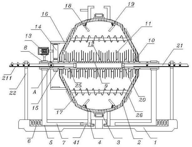
[0040] In the above-mentioned step 3, the high-speed shearing equipment includes a base 1, and a shearing tank 2 is arranged above the base 1, and the upper and lower ends of the shearing tank 2 are equipped with valve material guide ports 3, and two...
Embodiment 2
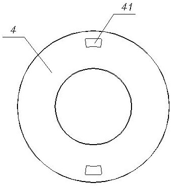
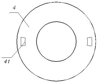
[0042] see Figure 1-5 In the traverse rod 7, the bottom of the traverse rod 7 is installed in the positioning groove 5 through the traverse spring 6, and the top of the traverse rod 7 is fixed with an installation sleeve 8, and the embedded movable installation of the shearing sleeve 8 Shaft 9, the middle of the shearing shaft 9 is located in the shearing tank 2, and the middle of the shearing shaft 9 is sleeved with a shearing blade 10 distributed in a spiral shape, and the shearing shaft 9 and the shearing blade 10 are welded with shearing blades. The cutting blade 11 is provided with a capillary centrifugal hole 12 at an equal angle in the space outside the middle part of the shear shaft 9; a push plate 41 is fixed on the outside of the positioning ring 4, and the cross-section of the positioning ring 4 is designed in a "匚" shape structure, and the positioning The ring 4 fits and slides in the positioning groove 5, two positioning rings 4 are symmetrically arranged on the ...
Embodiment 3
[0044] see figure 1 and Image 6 , the piston 20, the piston 20 is installed in the shear shaft 9, and the outer end of the piston 20 is fixed with a push rod 21, and the top of the push rod 21 is embedded and movably installed with a fixed block 24 through a telescopic spring 23, one end of the fixed block 24 It is located in the fixing groove 25, and the fixing groove 25 is opened on the inner wall of the shear shaft 9. One end of the push rod 21 runs through the top of the vertical rod 22, and the vertical rod 22 is fixed at the top edge of the base 1. A movable column 211 is installed in the embedded movable, and a pull rope 212 is fixed between the movable column 211 and the fixed block 24. The fixed block 24 elastically slides on the push rod 21 through the expansion spring 23, and the top of the fixed block 24 has a right-angled trapezoid structure. design, and the top of the fixed block 24 is engaged with the fixed groove 25, and the fixed groove 25 is designed in a r...
PUM
 Abstract
Description
Claims
Application Information
 - R&D Engineer
- R&D Manager
- IP Professional
- Industry Leading Data Capabilities
- Powerful AI technology
- Patent DNA Extraction
Browse by: Latest US Patents, China's latest patents, Technical Efficacy Thesaurus, Application Domain, Technology Topic.
© 2024 PatSnap. All rights reserved.Legal|Privacy policy|Modern Slavery Act Transparency Statement|Sitemap