Adjustable turnover formwork at concrete floor slab construction joint

A technology for construction joints and concrete, which is applied in the direction of formwork/formwork components, formwork/formwork/work frame, formwork/formwork/work frame connectors, etc., which can solve the problems of poor concrete forming effect, difficult process, and cumbersome process and other problems to achieve the effect of improving the performance of anti-leakage slurry, shortening the construction period and saving costs

Active Publication Date: 2022-03-08
CHINA SHANXI SIJIAN GRP
View PDF14 Cites 1 Cited by
  • Summary
  • Abstract
  • Description
  • Claims
  • Application Information

AI Technical Summary

Problems solved by technology

In the prior art, the inner mold for horizontal rib insertion is mostly replaced by lightweight fillers such as polystyrene boards, or barbed wire. Whether it is lightweight fillers such as polystyrene boards or wire mesh, the post-processing procedures are cumbersome and not fireproof. , high cost, serious grout leakage, poor concrete forming effect, which brings difficulties to the follow-up process

Method used


Image

  • Adjustable turnover formwork at concrete floor slab construction joint
  • Adjustable turnover formwork at concrete floor slab construction joint
  • Adjustable turnover formwork at concrete floor slab construction joint

Examples


Embodiment 1

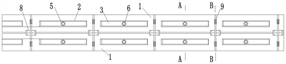
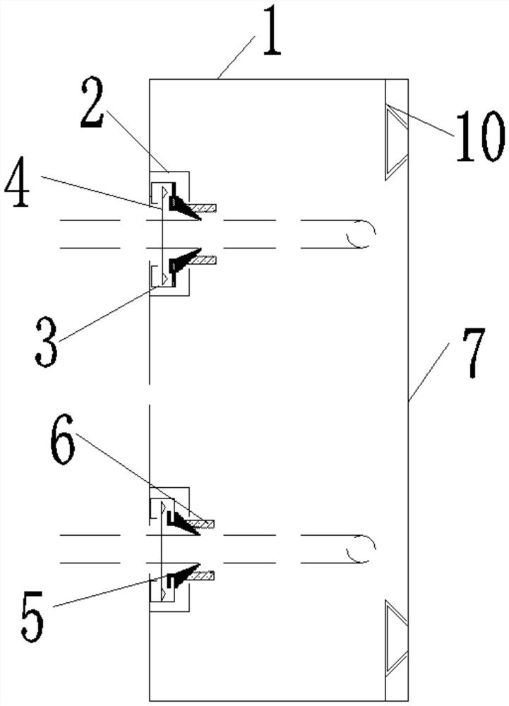
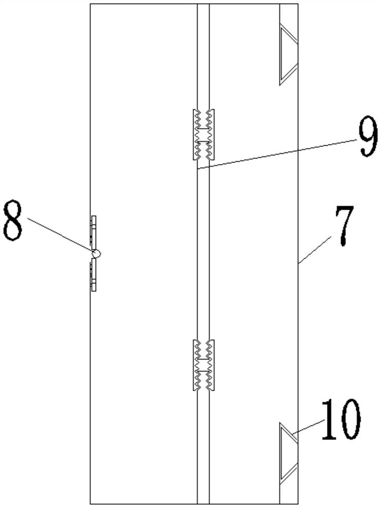
[0026] Embodiment 1: An adjustable turnover formwork at the construction joint of a concrete floor, including two groups of anti-leakage slurry steel formwork 1 arranged mirror-symmetrically along the horizontal direction. The vertical panels of the slurry steel formwork 1 are hinged by hinges 8, and the adjacent sides of the upper and lower leak-proof slurry steel formworks 1 are provided with leak-proof slurry strips to block the gap between the two leak-proof slurry steel formworks 1. Leakage, the horizontal panels of the two sets of leak-proof slurry steel formwork 1 are connected as a whole through the connecting sealing plate 7, the connecting sealing plate 7 is arranged on the back side of the hinge 8, and there are several equal distances on the vertical panel of the leak-proof slurry steel formwork 1. The strip-shaped opening, the leak-proof slurry steel template 1 is fixed with a profiled steel plate groove 2 at the position corresponding to the strip-shaped opening, ...

Embodiment 2

[0036] Embodiment 2: In Embodiment 1, there is also the problem that the gap between the rubber telescopic buckle 5 and the ribs may leak. Therefore, on the basis of Embodiment 1, this embodiment also includes: the rubber telescopic buckle 5 extends into the leak-proof One side of the slurry steel formwork 1 is provided with threads, and the rubber telescoping buckle 5 is connected with the anti-leakage slurry nut 6 by threads. After the steel bar is inserted into the formwork through the rubber telescopic buckle 5, turn the anti-leakage slurry nut 6 to move the anti-leakage slurry nut 6 to the direction of the anti-leakage slurry steel formwork 1, thereby driving the rubber telescopic buckle 5 to squeeze in the direction of inserting the bar and sealing the rubber The gap between the telescopic buckle 5 and the inserted rib ensures the anti-leakage slurry effect of the device. The adjustable range of the rubber telescopic buckle 5 is 6-30mm.

[0037] When installing this dev...


PUM


Abstract

The invention relates to the technical field of concrete construction, in particular to an adjustable turnover formwork at a concrete floor slab construction joint. Comprising two groups of anti-slurry-leakage steel formworks which are arranged in a mirror symmetry mode in the horizontal direction, the section of each anti-slurry-leakage steel formwork is in an L shape, vertical panels of the two groups of anti-slurry-leakage steel formworks are hinged through hinges, and horizontal panels of the two groups of anti-slurry-leakage steel formworks are connected into a whole through connecting sealing plates. A plurality of strip-shaped openings are formed in a vertical panel of the slurry leakage steel formwork at equal intervals, profiled steel sheet grooves are fixedly formed in the positions, corresponding to the strip-shaped openings, of the interior of the slurry leakage prevention steel formwork, slurry leakage prevention sliding plates used for leaking the strip-shaped openings are arranged in the profiled steel sheet grooves in a sliding mode, holes are formed in the slurry leakage prevention sliding plates, and rubber telescopic buckles are fixedly embedded in the holes. The device is good in supporting performance, excellent in grout leakage prevention performance and capable of being quickly mounted, dismounted and recycled, cost is remarkably saved, and the construction period is shortened. The adjustable turnover formwork is mainly applied to the aspect of the concrete construction joint adjustable turnover formwork.

Description

technical field [0001] The invention relates to the technical field of concrete construction, and more specifically relates to an adjustable turnover formwork at the construction joint of a concrete floor slab. Background technique [0002] The horizontal insertion of concrete bars is to facilitate the later process requirements. Before pouring the foundation, a section of steel bars is embedded in the foundation in advance according to the size and quantity of structural steel bars. In the prior art, the inner mold for horizontal rib insertion is mostly replaced by lightweight fillers such as polystyrene boards, or barbed wire. Whether it is lightweight fillers such as polystyrene boards or wire mesh, the post-processing procedures are cumbersome and not fireproof. , high cost, serious grout leakage, and poor concrete forming effect bring difficulties to the follow-up process. Contents of the invention [0003] In order to overcome the deficiencies in the above-mentioned...

Claims


Application Information

Patent Timeline
Patent Type & Authority Applications(China)
IPC IPC(8): E04G11/36E04G9/08E04G17/04E04G17/00
CPCE04G11/365E04G9/083E04G17/04E04G17/005E04G17/007
Inventor 田文俊李浩张元旭李晋卢鹏李奇王艳丽
Owner CHINA SHANXI SIJIAN GRP
Why Eureka
Try Eureka