Supercharge Your Innovation With Domain-Expert AI Agents!

Bridge steel box girder production system and bridge steel box girder production method

A production system and steel box girder technology, applied in the direction of gas flame welding equipment, plasma welding equipment, arc welding equipment, etc., can solve the problems of workers' fatigue, work-related accidents, low production efficiency, etc., and achieve the reduction of repair rate and intelligentization High degree, the effect of improving production efficiency and productivity

Inactive Publication Date: 2022-03-11
WUHAN FARLEYLASERLAB CUTTING SYST ENG
View PDF0 Cites 0 Cited by
  • Summary
  • Abstract
  • Description
  • Claims
  • Application Information

AI Technical Summary

Problems solved by technology

For the production process of the steel box girder mentioned above, although there are processes that can be completed by mechanized equipment, such as the handling and blanking of plates, etc., steps such as assembly and welding can only be completed by manual operations, such as through traditional The manual welding is used to complete the plate welding, the labor intensity of the workers is high, and in the high-intensity work, the workers are prone to fatigue, which leads to unstable welding quality and may even cause work-related accidents
[0003] At the same time, since many steps can only be completed manually, it cannot form a highly intelligent and mechanized assembly line production process, resulting in low production efficiency and unable to meet the requirements for mass and efficient production of steel box girders

Method used


Image

  • Bridge steel box girder production system and bridge steel box girder production method
  • Bridge steel box girder production system and bridge steel box girder production method
  • Bridge steel box girder production system and bridge steel box girder production method

Examples


Embodiment 1

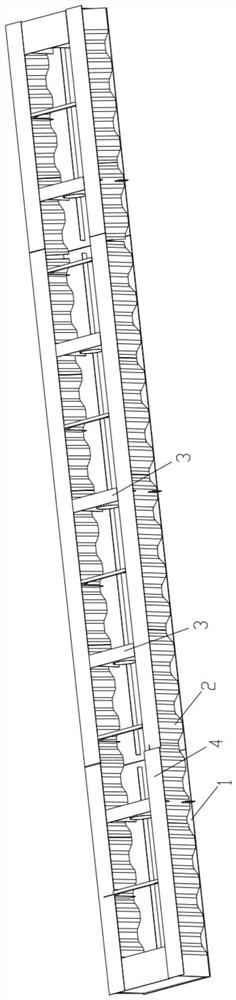
[0033] This embodiment provides a bridge steel box girder production equipment, wherein, such as figure 1 As shown, the bridge steel box girder includes: a bottom plate 1, a corrugated steel web 2 vertically connected to the bottom plate 1 at the top, a connecting plate 4 vertically connected to the bottom of the corrugated steel web 2, and a connecting plate vertically connected to the bottom plate 1 Separator 3: There are two groups of corrugated steel webs 2, and they are arranged in parallel, each partition 3 is located between two groups of corrugated steel webs 2, and each partition 3 is connected to the Web 2 is vertical or nearly vertical.

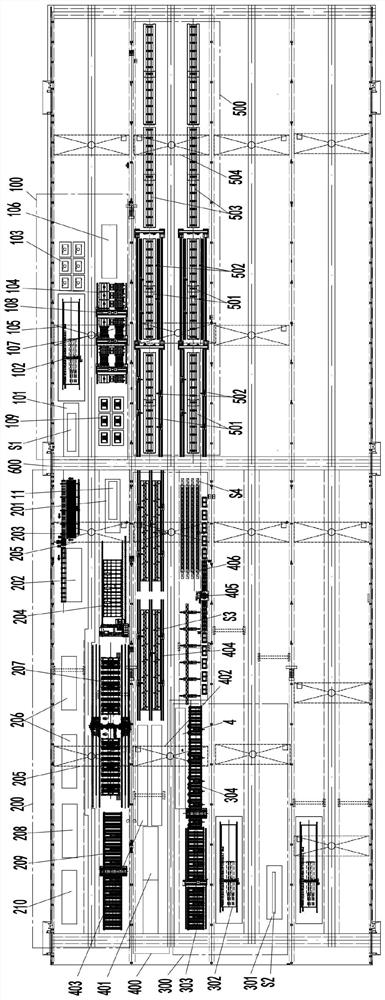
[0034] Such as figure 2 As shown, the bridge steel box girder production system includes:

[0035] A partition unit station 100, which is used to obtain the steel box girder partition 3;

[0036] Base unit station 200, which is used to obtain the steel box girder base 1;

[0037] Connecting plate unit station 300, which is use...

Embodiment 2

[0077] The difference between this embodiment and embodiment 1 is that, as Figure 7-8 As shown, the top web assembly station 403 includes: a connecting plate support mechanism 43, which is used to support the connecting plate 4, and can drive the moving of the connecting plate 4, so that the two length sides of the connecting plate 4 are in line with the The distance of the horizontal plane is different, thus making the connecting plate 4 inclined relative to the horizontal plane, for example, as Figure 8 As shown, the distance H between the first length side 42 of the connection board 4 and the horizontal plane P is smaller than the distance H' between the second length side 42' and the horizontal plane, thus making the connection board 4 in an inclined state relative to the horizontal plane P; the connection board abutting mechanism 44, which is used to resist a length side (such as the first length side 42) of the connecting plate 4 with a relatively small distance from t...

Embodiment 3

[0093] At present, the welding of the corrugated steel web and the connecting plate is mostly completed by manual welding. However, due to the long length of the weld of the corrugated steel web (the length of the corrugated steel web can reach 30m), the welder needs to work for a long time. , overloaded welding work can be completed, but long-term exposure to the welding environment with loud noise and toxic fumes will cause irreversible damage to the health of employees, and the long training period and insufficient number of qualified welders lead to production capacity that cannot meet the market need. Thus, the present embodiment differs from Embodiment 1 or 2 in that, as Figure 10 As shown, the top web welding station 404 includes:

[0094] The first guide rail 4041, the second guide rail 4042, and the third guide rail 4043 arranged parallel to each other, and the second guide rail 4042 is located between the first guide rail 4041 and the third guide rail 4043; meanwhi...


PUM


Abstract

The invention discloses a bridge steel box girder production system and method, and the system comprises a partition plate unit station which is used for obtaining a steel box girder partition plate; the bottom plate unit station is used for obtaining a steel box girder bottom plate; the plate receiving unit station is used for obtaining steel box girder receiving plates; the top web unit station is used for completing connection of the corrugated steel web and the connecting plate so as to obtain a top web; and the integral assembly work station is used for receiving the partition plate, the bottom plate and the top web plate and assembling and welding the partition plate, the bottom plate and the top web plate to obtain the steel box girder. The steel box girder production line is high in intelligence and mechanization, the steps of orderly splicing, welding and the like of steel box girder components can be achieved, and the production efficiency can be greatly improved on the basis that the quality of the steel box girder is guaranteed.

Description

technical field [0001] The invention relates to the field of equipment manufacturing, in particular to a bridge steel box girder production system and a bridge steel box girder production method. Background technique [0002] The production and manufacture of steel box girders involves many processes, including handling and blanking, assembling and welding of partitions, bottom plates, top webs and other plates. For the production process of the steel box girder mentioned above, although there are processes that can be completed by mechanized equipment, such as the handling and blanking of plates, etc., steps such as assembly and welding can only be completed by manual operations, such as through traditional Manual welding is used to complete the plate welding, the labor intensity of the workers is high, and in the high-intensity work, the workers are prone to fatigue, which leads to unstable welding quality, and may even cause work-related accidents. [0003] At the same t...

Claims


Application Information

Patent Timeline
IPC IPC(8): B23K28/02B23K9/12B23K9/32B23K7/00B23K7/10B23K10/00
CPCB23K28/02B23K9/12B23K9/32B23K7/00B23K7/10B23K10/00
Inventor 钟熠杨乐天甘春明陈谢国邢宏伟吴苶
Owner WUHAN FARLEYLASERLAB CUTTING SYST ENG
Features
  • R&D
  • Intellectual Property
  • Life Sciences
  • Materials
  • Tech Scout
  • Unparalleled Data Quality
  • Higher Quality Content
  • 60% Fewer Hallucinations
Learn More