Arrangement method of strong dynamic pressure coal seam roadway along middle reserved wall body

A technology of roadway layout and wall body, which is applied in earth-moving drilling, mine/tunnel ventilation, surface mining, etc., can solve the problems of low efficiency of gob-side entry retaining, high reuse difficulty, and roadway variability in coal mines.

Pending Publication Date: 2022-03-11
CCTEG COAL MINING RES INST +1
View PDF0 Cites 0 Cited by
  • Summary
  • Abstract
  • Description
  • Claims
  • Application Information

AI Technical Summary

Problems solved by technology

[0005] For this reason, the purpose of this application is to propose a method of roadway layout for strong dynamic pressure coal seam along the reserved wall in the middle, which adopts a new roadway layout technology combining the reserved wall in the middle and the pressure relief in advance, and has a high rate of one-time forming of the roadway, The deformation of the roadway is small, the end is easy to maintain, the mining efficiency of the working face is high, the input of roadway retaining equipment and materials is reduced, and the amount of roadway excavation is reduced. It is suitable for high-gas mines with strong mining dynamic pressure and large roadway deformation. Low efficiency of gob-side roadway retention in coal mines, variability of roadways, difficulty in reuse, etc.

Method used


Image

  • Arrangement method of strong dynamic pressure coal seam roadway along middle reserved wall body
  • Arrangement method of strong dynamic pressure coal seam roadway along middle reserved wall body
  • Arrangement method of strong dynamic pressure coal seam roadway along middle reserved wall body

Examples


Embodiment Construction

[0029] Embodiments of the present application are described in detail below, examples of which are shown in the drawings, wherein the same or similar reference numerals denote the same or similar elements or elements having the same or similar functions throughout. The embodiments described below by referring to the figures are exemplary, and are only for explaining the present application, and should not be construed as limiting the present application. On the contrary, the embodiments of the present application include all changes, modifications and equivalents falling within the spirit and scope of the appended claims.

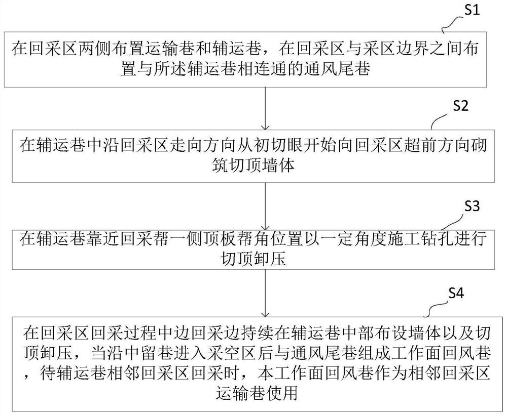
[0030] figure 1 It is a flow chart of a method for arranging roadways in strong dynamic pressure coal seams along a central reserved wall proposed by an embodiment of the present application.

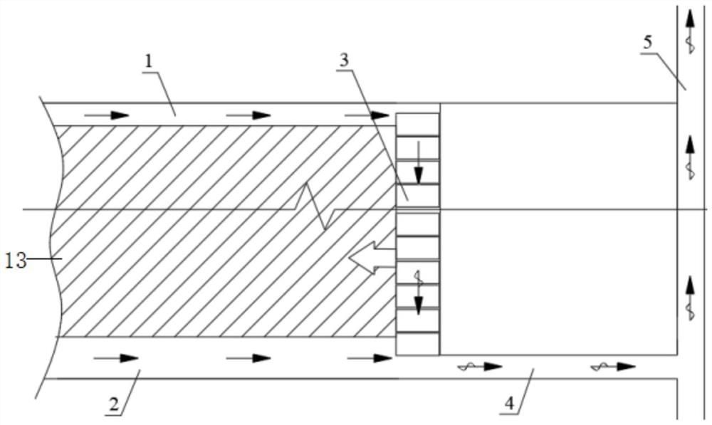
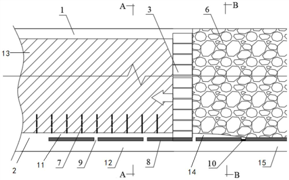
[0031] The average thickness of the coal seam in a high-gas mine is 3.6m. It is a medium-hard coal seam with an inclination angle of 1-3°. The roof is a relatively ...


PUM


Abstract

The invention provides a method for arranging a strong dynamic pressure coal seam roadway along a middle reserved wall. The method comprises the steps that a transportation roadway and an auxiliary transportation roadway are arranged on the two sides of a stoping area, and a ventilation tail roadway communicating with the auxiliary transportation roadway is arranged between the stoping area and the boundary of the stoping area; a wall body with a cut top is built in the auxiliary transportation roadway in the length direction from the initial cut hole by a certain distance, so that the wall body divides the auxiliary transportation roadway into a reserved roadway and another middle retaining roadway; roof cutting and pressure relief are conducted at a certain angle at the top plate slope angle position, close to one side of the stoping slope, of the auxiliary transportation roadway; in the stoping process of the stoping area, wall laying and roof cutting pressure relief are continuously conducted in the middle of the auxiliary transportation roadway while stoping is conducted, a working face air return roadway is formed by a gob behind the working face along the middle retained roadway and the ventilation tail roadway, and when the adjacent working face is stoped, the working face air return roadway is used as a transportation roadway. A roadway arrangement process combining middle wall reserving and advanced pressure relief is adopted, so that the one-time forming rate of a roadway is high, the deformation of the roadway is small, and the ends are easy to maintain.

Description

technical field [0001] The present application relates to the technical field, in particular to a method for arranging roadways in strong dynamic pressure coal seams along a centrally reserved wall. Background technique [0002] Retaining roadways along the middle is a key technology to solve the problem of gas exceeding the limit. It is widely used in the mining area of ​​high gas mines. Generally, flexible molded concrete walls and single-body cut roofs are used on the side of the air return roadway of the coal mining face along the edge of the gob. Columns and other methods are used to maintain the original mining roadway, forming a Y-shaped ventilation mode with two inlets and one return, canceling the upper corner of the return air lane on the working face, and avoiding the problem of gas overrun. The reserved roadway can be reused after re-maintenance, and can be used for the next adjacent working face. Sectional coal pillars are canceled, which can save a lot of coal ...

Claims


Application Information

Patent Timeline
Patent Type & Authority Applications(China)
IPC IPC(8): E21C41/18E21F1/00E21F13/06
CPCE21C41/18E21F1/006E21F13/06
Inventor 于健浩薛吉胜司伟明赵铁林刘伟韬马兆瑞潘黎明郭建力宋晓寒
Owner CCTEG COAL MINING RES INST
Why Eureka
Try Eureka