
Throwable valveless electromagnetic pump

A technology of electromagnetic pump and pump body, applied in the field of electromagnetic pump, can solve the problems of low efficiency, complex manufacturing process and structure, limited spring life, etc., and achieve the effects of simple manufacturing, simple manufacturing process and increasing working frequency

Active Publication Date: 2022-03-11
气味王国(山东)科技有限公司 +1
View PDF3 Cites 0 Cited by
  • Summary
  • Abstract
  • Description
  • Claims
  • Application Information

AI Technical Summary

Problems solved by technology

[0004] The main purpose of the present invention is to provide a throwable valveless electromagnetic pump, which can effectively solve the problem in the background technology: there are mainly two types of existing electromagnetic drive pumps. The coil is fed with alternating current, and the permanent magnet is driven by the external magnetic force to move up and down. Through the resistance in the two directions of the diffusion port and the nozzle structure, the liquid is pumped in from the liquid inlet and pumped out from the liquid outlet; the second type is an armature electromagnetic pump. The spring is compressed when the ring is excited, and the spring is reset when the magnet is deenergized. The spring life of the armature electromagnetic pump is limited, and it will fail as the number of uses increases. In addition, there is a problem of high energy consumption and high frequency cannot be achieved; Valves are divided into valved micropumps and valveless micropumps. The manufacturing process and structure of valved micropumps are more complicated, and their efficiency is lower than that of valveless micropumps. At present, most valveless micropumps are driven by piezoelectric films. Technical problem with high voltage problem

Method used


Image

  • Throwable valveless electromagnetic pump
  • Throwable valveless electromagnetic pump
  • Throwable valveless electromagnetic pump

Examples


Embodiment Construction

[0032] In order to make the technical means, creative features, goals and effects achieved by the present invention easy to understand, the present invention will be further described below in conjunction with specific embodiments.

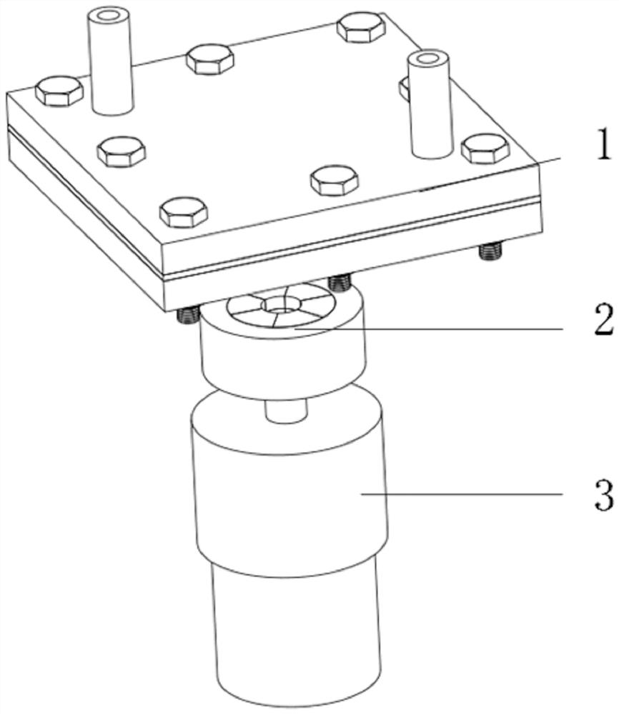
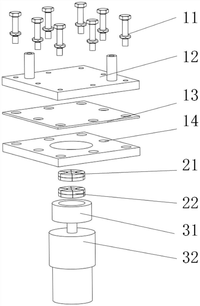
[0033] Such as Figure 1-16 As shown, a throwable valveless electromagnetic pump includes a pump body 1, a multi-pole ring magnet 2 and a drive structure 3. The pump body 1 is installed on the top of the multi-pole ring magnet 2, and the drive structure 3 is arranged on the multi-pole ring magnet. 2 bottom.

[0034] The pump body 1 includes a bolt assembly 11, a pump body part 12, an elastic film 13 and a cover plate 14. The elastic film 13 is installed between the cover plate 14 and the pump body part 12. The bolt assembly 11 is composed of a bolt and a nut, and the bolt runs through the pump. After the body part 12, the elastic film 13 and the cover plate 14 are screwed with the nut.

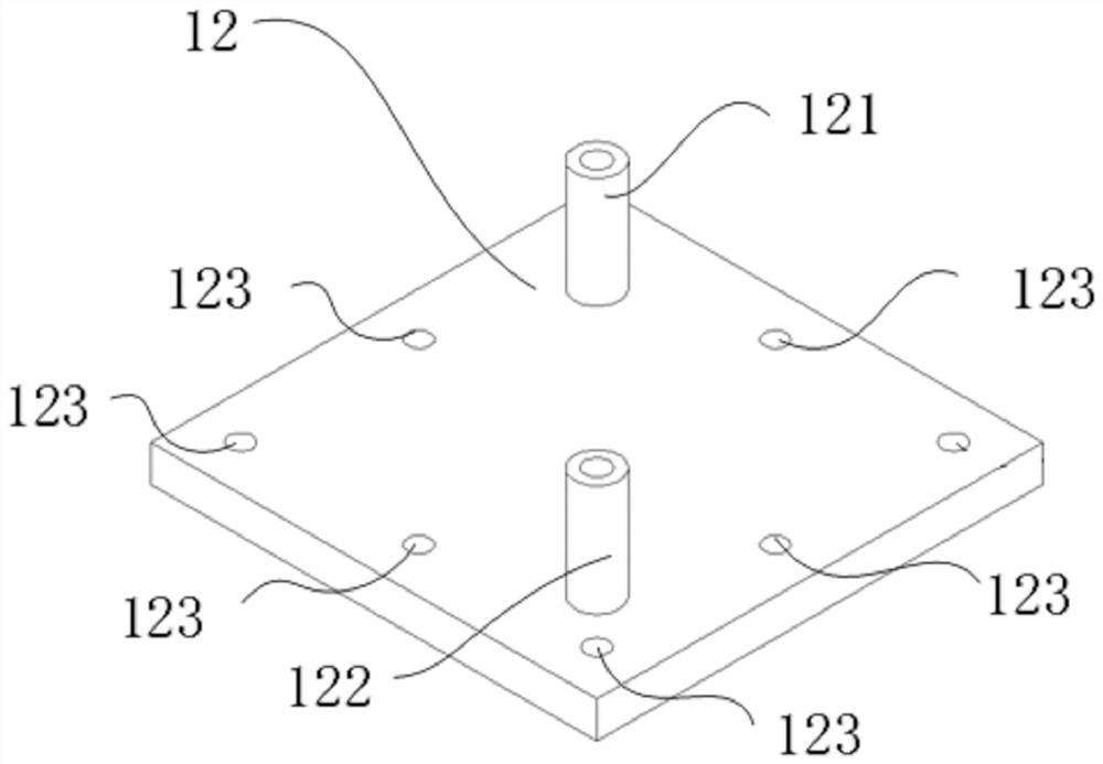
[0035] The upper diagonal position of the pump body part 1...


PUM


Abstract

The invention discloses a jettisonable valveless electromagnetic pump, which belongs to the field of electromagnetic pumps and comprises a pump body, a multi-pole annular magnet and a driving structure, and the pump body is mounted at the top of the multi-pole annular magnet. According to the jettisonable valveless electromagnetic pump, the scheme that the pump body and the driving part are separated is adopted, the pump body can be discarded and replaced, the driving device can be repeatedly used, the jettisonable valveless electromagnetic pump is suitable for occasions where fluid is polluted and the pump body needs to be replaced, and the working frequency of the pump body can be improved through improvement of the driving mode; the motor drives the multi-stage annular magnet to rotate and drives the other multi-stage annular magnet bonded with the pump body film to move up and down, so that the volume change of the cavity is realized, and the pumping-in and pumping-out of fluid are completed. The problem that a traditional electromagnetic pump is not high in frequency due to limitation of an electromagnetic coil is solved, the inflow hole and the outflow hole are conical, liquid is pumped in and out in one direction due to the fact that resistance on the two sides of inflow and outflow fluid is different, additional valve control is not needed, and the manufacturing process is simpler.

Description

technical field [0001] The invention relates to the field of electromagnetic pumps, in particular to a throwable valveless electromagnetic pump. Background technique [0002] Micropumps are widely used in microfluidic systems, and are responsible for distributing and transmitting liquid flow. It is a micro-actuator that includes multiple driving methods, such as piezoelectric, electrostatic, pneumatic, and electromagnetic drives. There are currently two Form of electromagnetically driven micropumps: one is electromagnetically driven micropumps, and the other is magnetic fluid driven micropumps, both of which are driven by magnetic fields to realize the function of micropumps to transport liquids. Electromagnetically driven micropumps are mechanical micropumps. The electromagnet generates driving force, which has the advantages of convenient control, low voltage, simple working principle, and large output force, but also has the disadvantages of complex structure, high produc...

Claims


Application Information

Patent Timeline
Patent Type & Authority Applications(China)
IPC IPC(8): F04B43/04F04B53/16
CPCF04B43/043F04B53/16
Inventor 韩冬邓闰祎卢方黄剑炜郑逸扬
Owner 气味王国(山东)科技有限公司
Learn More