

Probe for phase change detection
A technology for detecting containers and media, which is applied in the field of probes for detecting phase changes in containers, and can solve problems such as sensor intrusion, complicated cost, and sensor failure to piggage
- Summary
- Abstract
- Description
- Claims
- Application Information
AI Technical Summary
Problems solved by technology
Method used
Image

Examples
Embodiment Construction
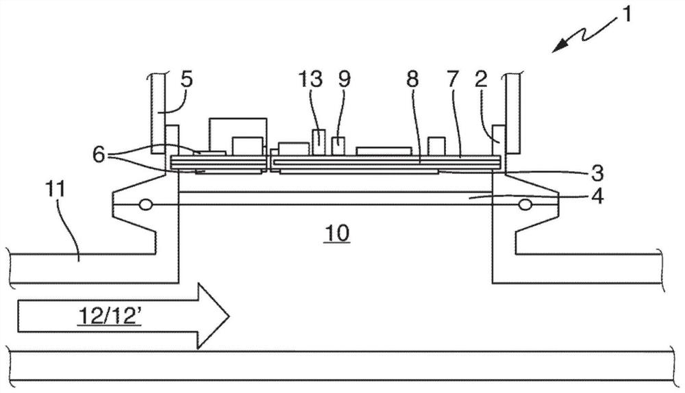
[0027] The claimed probe is denoted in its entirety by reference number 1, and in figure 1 shown in .
[0028] A hermetically sealed probe 1 of hygienic design is presented which detects phase boundaries of different liquid media in industrial processes by means of microwave technology. “Gas-tight” is understood in this context to mean that fluids such as the medium to be measured, air or dust cannot penetrate from the outside. Also does not include any electrical feedthroughs.
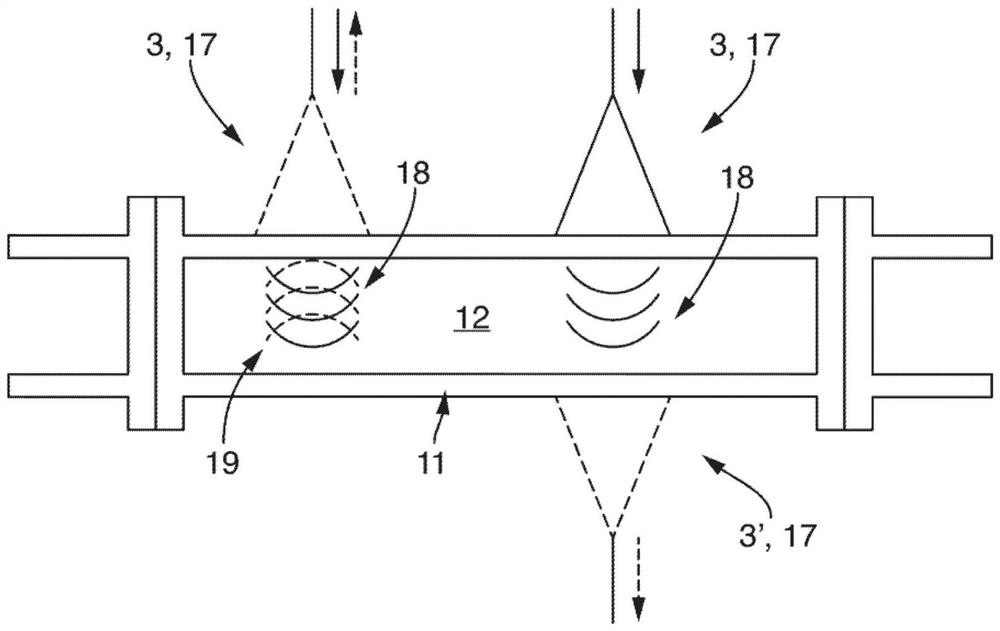
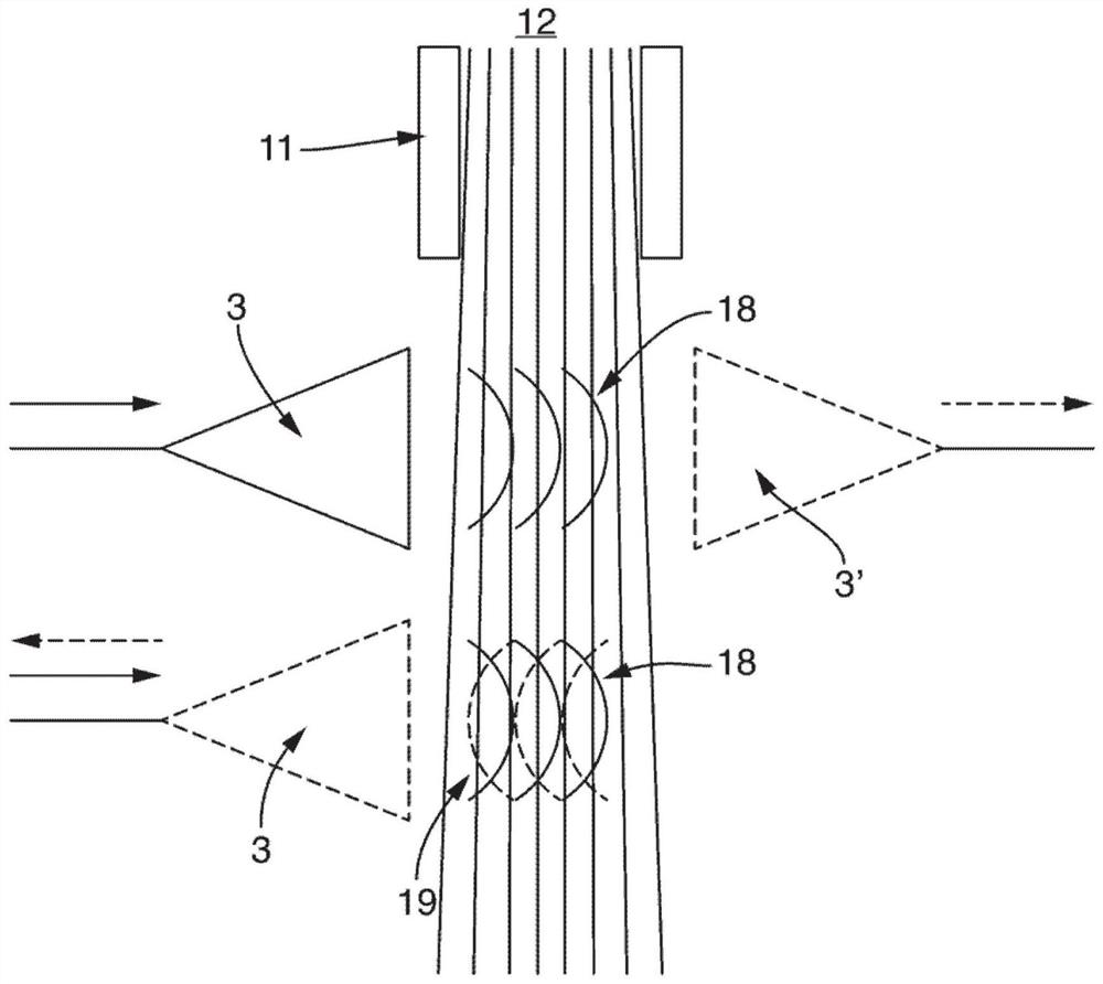
[0029] The probe 1 operates in the frequency range of 100 to 10000 MHz, but preferably in the range of 500 to 3000 MHz. The probe operates at at least one frequency.
[0030] In one embodiment, instead of using only one measurement frequency, switching between several fixed frequencies occurs, or the measurement frequency is continuously changed within a defined range. Due to the different penetration depths or the available analyzable volume ranges, then, in addition to detecting the phase bounda...
PUM
 Abstract
Description
Claims
Application Information