Ranging radar system based on same-frequency perception and opportunity emission and implementation method

A technology of ranging radar and opportunity, applied in radio wave measurement systems, measuring devices, and re-radiation, etc., can solve problems such as disturbing the normal operation of ranging radar, reducing radar functions, and burning radar receivers, so as to improve the electromagnetic environment. The effect of adaptability, high reliability and easy method

Active Publication Date: 2022-03-11
中国人民解放军火箭军工程大学
View PDF9 Cites 0 Cited by
  • Summary
  • Abstract
  • Description
  • Claims
  • Application Information

AI Technical Summary

Problems solved by technology

However, they all face the interference problem of complex electromagnetic environment. The background electromagnetic interference signal or active interference signal in the environment enters the radar receiver through radiation or scattering, which reduces the signal-to-noise ratio at the output of the radar receiver, which may cause the radar function to decrease or lose
Moreover, with the wide application of multi-band electronic equipment and the development of electronic devices, the possibility of mutual interference of the same frequency signals between electronic equipment is increasing, which will destroy and disrupt the normal operation of the ranging radar, and the super strong interference signal may even burn out the radar receiver
[0003] At present, many anti-jamming methods have appeared to improve the anti-interference ability of ranging radar. However, when the ranging radar based on radio detection is subjected to high-power co-frequency interference, the receiver is damaged or blocked and the system function cannot be realized. The problem still cannot be effectively solved. In this context, some equipment can only fall back to laser detection or composite radar
However, laser detection radar is easily affected by natural environments such as smog, rain and snow, clouds, and strong light. The composite system greatly increases the complexity of the system.

Method used


Image

  • Ranging radar system based on same-frequency perception and opportunity emission and implementation method
  • Ranging radar system based on same-frequency perception and opportunity emission and implementation method

Examples


Embodiment 1

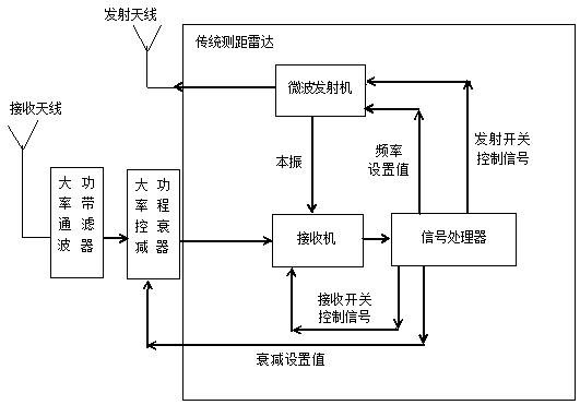
[0074] This embodiment provides a ranging radar system based on co-frequency perception and opportunity emission, such as figure 2 As shown, including transmitting antenna, receiving antenna, high-power bandpass filter, high-power programmable attenuator, microwave transmitter, receiver and signal processor.

[0075] In this embodiment, the ranging radar system is a ranging radar with a frequency modulation system, and the main parameters are: the operating frequency range of the ranging radar is 2GHz±1GHz; the gain of the transmitting antenna and the receiving antenna are both 5dB in the operating frequency range The gain is not greater than 0dB below 0.5GHz, and the gain is not greater than -5dB above 3.5GHz; the working center frequency of the microwave transmitter can be adjusted in two gears, respectively 2GHz and 1.5GHz, and the linear frequency modulation bandwidth is 100MHz; the receiver monitors the input RF signal Limiting, amplifying, filtering, mixing with the loc...


PUM


Abstract

The invention discloses a range radar system based on co-frequency perception and opportunity emission and an implementation method. The range radar system comprises a traditional range radar and a co-frequency sensor. The same-frequency sensor comprises a high-power band-pass filter and a high-power programmable attenuator and shares an antenna, a receiver and a signal processor of a traditional ranging radar, the antenna, the high-power band-pass filter and the high-power programmable attenuator are connected in sequence, and the signal processor comprises a same-frequency sensing and opportunity transmitting module; the high-power band-pass filter is used for filtering out-of-band signals, and the high-power programmable attenuator is used for controlling the amplitude of radio frequency signals. The radar system can realize the detection function under the background of strong electromagnetic interference, especially solves the problem that the system function cannot be realized due to the fact that the receiver is damaged or blocked when the radar system is subjected to high-power same-frequency interference, not only retains the natural environment adaptability advantage of the radar system, but also improves the electromagnetic environment adaptability of the radar system.

Description

technical field [0001] The invention belongs to the technical field of radio detection radar, and in particular relates to a ranging radar system based on same-frequency perception and opportunistic emission and an implementation method. Background technique [0002] Ranging radar has become an indispensable electronic device for many aircrafts and vehicles, and is widely used in daily life. However, they all face the interference problem of complex electromagnetic environment. The background electromagnetic interference signal or active interference signal in the environment enters the radar receiver through radiation or scattering, which reduces the signal-to-noise ratio at the output of the radar receiver, which may cause the radar function to decrease or lose. Moreover, with the wide application of multi-band electronic equipment and the development of electronic devices, the possibility of mutual interference of the same frequency signals between electronic equipment i...

Claims


Application Information

Patent Timeline
IPC IPC(8): G01S13/34G01S7/02G01S13/00G01S13/10
CPCG01S13/34G01S13/10G01S13/003G01S7/023
Inventor 胡昌华陈若飞钟都都魏维伟何川杨剑肖开清赵升
Owner 中国人民解放军火箭军工程大学
Why Eureka
Try Eureka