Laminated composite electronic device and its producing method
An electronic device, lamination technology, applied in the manufacture of inductors/transformers/magnets, inductors, coils, etc., can solve the problem of impossible to obtain ceramics
- Summary
- Abstract
- Description
- Claims
- Application Information
AI Technical Summary
Problems solved by technology
Method used
Image

Examples
example 1
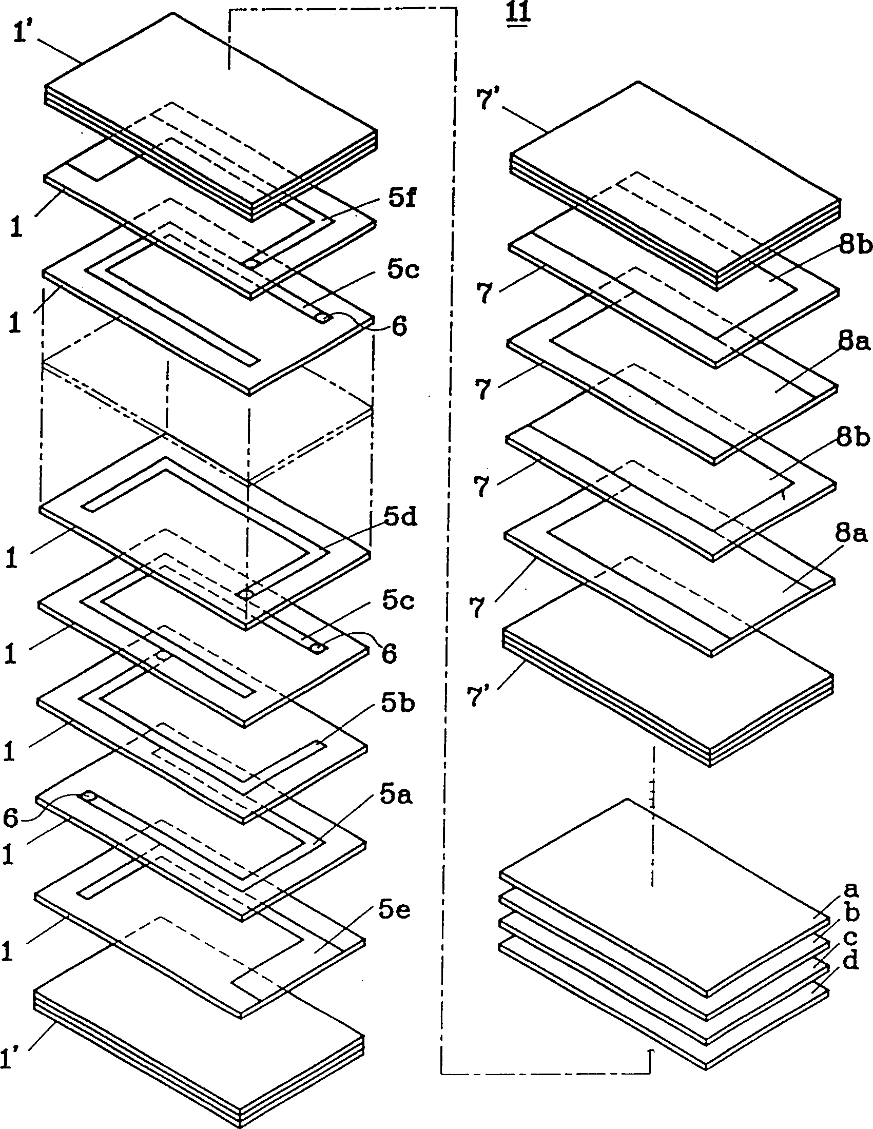
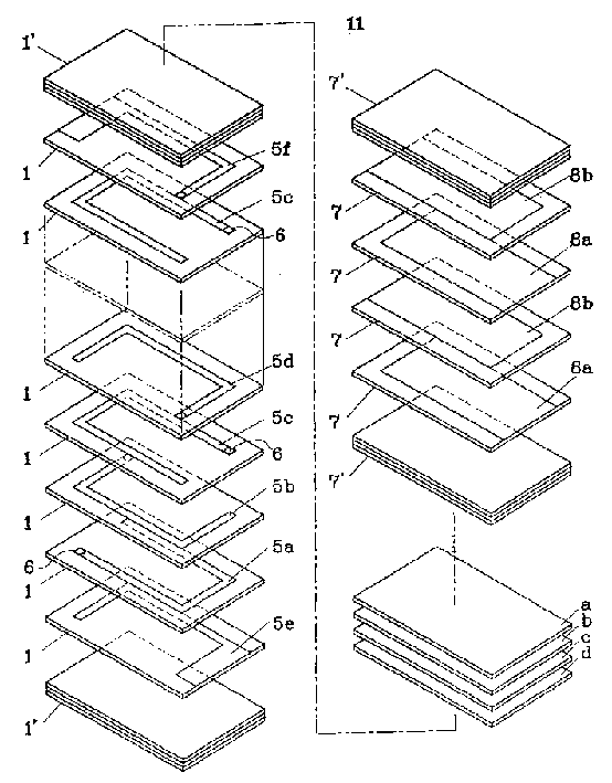
[0041] Press Fe 2 o 3 49mol%, NiO 42mol%, ZnO 42mol% and CuO 5mol% ratio of raw material powder prepared as ferrite magnetic powder, they were pre-fired at 680 ℃, and then dispersed in an organic binder to Preparation of magnetic slurry. The magnetic slurry was formed into a 30 µ thick magnetic ceramic green sheet by the doctor blade method. It will be mentioned below that the linear expansion coefficient of the magnetic ceramics formed after the magnetic ceramic green sheet is fired is 13.0×10 -6 / °C.
[0042] After a through hole is punched at a predetermined position of a part of the above-mentioned ceramic green sheet, a plurality of ring-shaped inner electrodes of silver paste aligned vertically and / or horizontally are printed, and the silver paste is drawn through the above-mentioned through hole to be printed on the through hole. inner surface to act as a conductor inside the via.
[0043] Prepare mainly containing FiO with above-mentioned same method 2 Dielectri...
example 2
[0058] In the above-mentioned embodiment 1, the ceramic blanks for forming the intermediate ceramic layers a, b, c and d were prepared by adding glass powder to the dielectric ceramics. The substitution methods in this embodiment are as shown in Table 3 The given quantity is added to the magnetic ceramic material with a linear expansion coefficient of 5×10 -6 / ℃ Si-B family glass powder (alumionborosili eat glass aluminoborosilicate glass) to prepare four kinds of magnetic - glass ceramic blanks A, B, C and D. Table 3 also lists the linear expansion coefficients of the intermediate glass-ceramic layers a, b, c and d prepared as above. In addition, for the sake of comparison, Table 3 also lists the linear expansion coefficients of magnetic ceramics and dielectric ceramics.
[0059] Further, in a similar manner to the above-mentioned Example 1, six kinds of laminated bodies 11, which are listed in Table 4, were prepared, using part of the above-mentioned magnetic-glass-ceramic...
example 3
[0064] In the above-mentioned Example 1, the ceramic green sheets for forming the intermediate ceramic layers a, b, c, and d were prepared by adding glass powder to the dielectric ceramic material. In this example, instead of the above-mentioned method, by changing the 2 o 3 , NiO, ZnO and CuO ferrite magnetic ceramics composition, mainly the content of ZnO and CuO, prepared for the formation of various magnetic ceramic green sheets listed in Table 5 from A to P intermediate ceramic layer. Table 5 also lists the linear expansion coefficients of various intermediate glass-ceramic layers formed by firing the above-mentioned magnetic ceramic green sheets A to P as mentioned below.
[0065] From the magnetic ceramics from A to P listed in Table 5 above, it can be seen that in the 2 o 3 , NiO, ZnO and CuO magnetic ceramics, the higher the content of NiO instead of CuO, the higher the coefficient of linear expansion. On the other hand, magnetic ceramics from I to N were found tha...
PUM
| Property | Measurement | Unit |
|---|---|---|
| thickness | aaaaa | aaaaa |
| thickness | aaaaa | aaaaa |
Abstract
Description
Claims
Application Information
 - R&D
- Intellectual Property
- Life Sciences
- Materials
- Tech Scout
- Unparalleled Data Quality
- Higher Quality Content
- 60% Fewer Hallucinations
Browse by: Latest US Patents, China's latest patents, Technical Efficacy Thesaurus, Application Domain, Technology Topic, Popular Technical Reports.
© 2025 PatSnap. All rights reserved.Legal|Privacy policy|Modern Slavery Act Transparency Statement|Sitemap|About US| Contact US: help@patsnap.com