Eureka AIR delivers breakthrough ideas for toughest innovation challenges, trusted by R&D personnel around the world.

Cooling device for magnetic stimulation system and magnetic stimulation system

A cooling device and magnetic stimulation technology, applied in transformer/inductor cooling, using the magnetic field generated by the coil, electromagnet, etc., can solve the problem of large power output, rising cost of MST equipment, and high heat generation of the magnetic stimulation coil of the magnetic stimulation host. problem, to achieve the effect of fast heat dissipation

Pending Publication Date: 2022-03-15
湖南华医电磁医学研究院有限公司
View PDF0 Cites 0 Cited by
  • Summary
  • Abstract
  • Description
  • Claims
  • Application Information

AI Technical Summary

Problems solved by technology

The superposition of multiple standard rTMS devices will not only lead to a significant increase in the cost of the MST device, but at the same time, due to the large power output of the magnetic stimulation device, the heat generated by the magnetic stimulation device is very concentrated, resulting in the heat generation of the magnetic stimulation host, especially the magnetic stimulation coil. very high
MST equipment generally outputs continuously for 10s or 8s, and it needs to be shut down for more than half an hour to cool down. The working efficiency of MST is very low.

Method used


Image

  • Cooling device for magnetic stimulation system and magnetic stimulation system
  • Cooling device for magnetic stimulation system and magnetic stimulation system
  • Cooling device for magnetic stimulation system and magnetic stimulation system

Examples


Embodiment 1

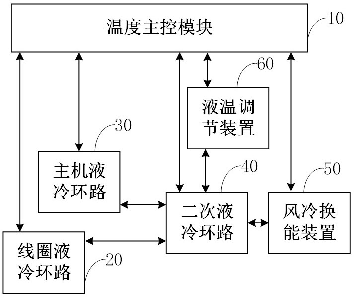
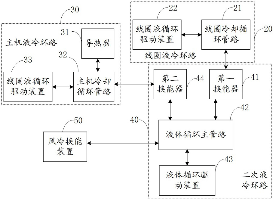
[0046] Please refer to figure 1 , is a schematic diagram of the structural connection of the cooling device in an embodiment, and the cooling device is used in a magnetic stimulation system. Wherein, the magnetic stimulation system includes a magnetic stimulation coil and a coil driving control device, the coil driving control device is used to provide driving power to the magnetic stimulation coil, and the magnetic stimulation coil is wound by a hollow metal tube. The cooling device includes a coil liquid cooling loop 20 , a secondary liquid cooling loop 40 and an air-cooled transducing device 50 . The coil liquid cooling loop 20 is used to transfer the thermal energy generated by the magnetic stimulation coil of the magnetic stimulation system to the secondary liquid cooling loop 40 . The secondary liquid cooling loop 40 is used to transfer the heat energy transferred from the coil liquid cooling loop to the air-cooled transducer device 50 in a liquid cooling manner. The a...


PUM


Abstract

The invention discloses a cooling device for a magnetic stimulation system and the magnetic stimulation system. The cooling device comprises a coil liquid cooling loop, a secondary liquid cooling loop and an air cooling transduction device. Wherein the secondary liquid cooling loop comprises a liquid circulation driving device, a liquid circulation main pipeline and a first transducer; the air cooling transduction device comprises a cooling fin and a fan which are arranged on the liquid circulation main pipeline; the coil liquid cooling loop comprises a coil liquid circulation driving device and a coil cooling circulation pipeline, the coil cooling circulation pipeline is communicated with a pipeline of the magnetic stimulation coil formed by winding the hollow metal pipe, and the coil cooling circulation pipeline and the liquid circulation main pipeline carry out heat energy interaction through the first transducer. The heat transfer between the hollow metal pipe of the magnetic stimulation coil and the coil cooling circulation pipeline is realized in a liquid cooling manner, so that the heat dissipation speed of the magnetic stimulation coil is higher, the magnetic stimulation coil is safer, and shielding and interference on electromagnetic signals emitted by the magnetic stimulation coil are avoided.

Description

technical field [0001] The present application relates to the technical field of magnetic stimulation systems, in particular to a cooling device for a magnetic stimulation system and a magnetic stimulation system. Background technique [0002] Transcranial Magnetic Stimulation (TMS) is an important technology in the field of biomedical engineering. It is based on the principle of brain electric field electromagnetic induction and can penetrate the skull through a high-field-strength pulsed electromagnetic field and act on a deep position. Nerve tissue can be used to stimulate and regulate nerves without penetrating the skin to install devices, which has the advantages of non-invasive and painless. The magnetic field used for TMS can be of sufficient strength and density to depolarize neurons, and when repeatedly applying TMS pulses, when the parameters of the magnetic stimulation (frequency, amplitude, pulse width, pulse width gradient, etc.) selected, Transcranial magnetic...

Claims


Application Information

Patent Timeline
Patent Type & Authority Applications(China)
IPC IPC(8): A61N2/04H01F7/06H01F27/10
CPCA61N2/006A61N2/02H01F7/06H01F27/10
Inventor 廖家华张朋罗满华王景信王鑫
Owner 湖南华医电磁医学研究院有限公司
Why Eureka
Eureka Blog
Learn More