Amplifier AM-AM distortion measurement method and system for base station
An AM-AM and base station system technology, applied in the field of amplifier AM-AM distortion measurement methods and systems, can solve the problems of temperature offset characteristics, large radiation dose, and the inability to directly describe the AM-AM curve, etc., to achieve accurate test results Intuitive, easy-to-operate effects
- Summary
- Abstract
- Description
- Claims
- Application Information
AI Technical Summary
Problems solved by technology
Method used
Image

Examples
Embodiment 1
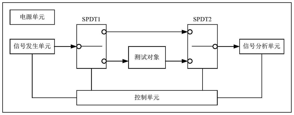
[0048] figure 2 It is a schematic diagram of an amplifier AM-AM distortion measurement system applicable to a base station provided in Embodiment 1 of the present application. Such as figure 2 As shown, the system is used to perform AM-AM test with the base station amplifier as the test object, the whole test process is automated, the operation is simple and the test result is accurate and intuitive. Such as figure 2 As shown, the system includes: a signal generation unit, a first switch SPDT1, a second switch SPDT2, a signal analysis unit, a control unit and a power supply unit, wherein:
[0049] In the signal generation unit, the output end is connected to the common end of the first switch SPDT1, the input end is connected to the control unit, and after the determined test signal is modulated to the current basic power signal, it is output from the output end according to the current output signal frequency;
[0050] The control terminal of the first switch SPDT1 is c...
Embodiment 2
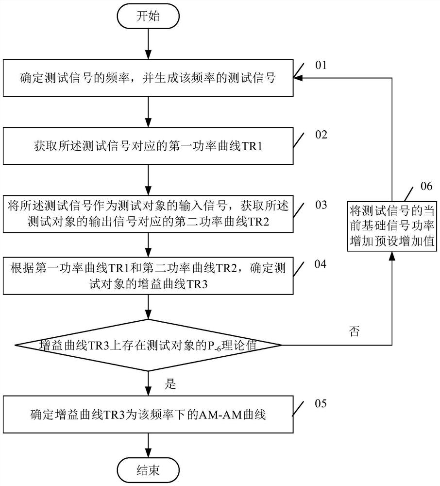
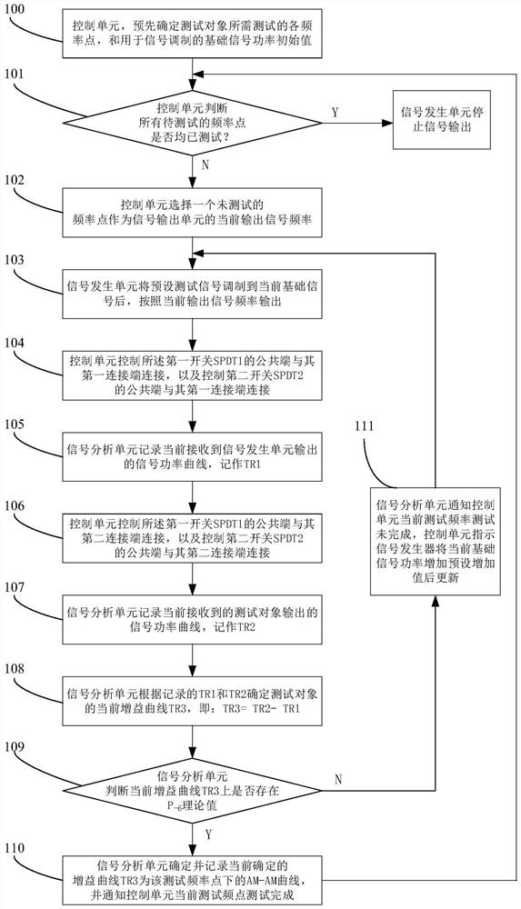
[0057] image 3 It is a flow chart of the AM-AM distortion test method for amplifiers applicable to base stations provided in Embodiment 2 of the present application. image 3 The shown method is based on the test system described in Embodiment 1. The present application provides an amplifier AM-AM distortion test method applicable to a base station. The test method is simple to implement and the test result is accurate and intuitive. Such as image 3 As shown, the test method includes:
[0058] Step 100: In the control unit, predetermine each frequency point to be tested by the test object and the initial value of the basic signal power used for signal modulation;
[0059] In this step, each frequency point is selected according to the scene frequency band used by the base station amplifier as the test object, and a certain number of frequency points are selected as test points based on the interval between the maximum value and the minimum value of the frequency band. For ...
Embodiment 3
[0084] Due to the current network environment, the base station system may have a power dynamic range due to back-off power usage, and may also have a power dynamic range due to certain specific scenarios, for example, in an FDD-LTE (Frequency Division Duplex LTE) system , the total power dynamic range between ETM3.1 and ETM2.0 is 20dB, plus the signal PAR=8dB requirement on the base station amplifier, the actual power dynamic range of the base station amplifier at this time is: 28dB. Therefore, in the present application, the above-mentioned embodiment 2 is improved so that AM-AM test can be performed on the base station amplifier that needs to be applied in the power dynamic range application scenario.
[0085] Figure 6 It is a flow chart of the AM-AM distortion test method for amplifiers applicable to base stations provided in Embodiment 3 of the present application. Figure 6 The shown method is based on the test system described in Embodiment 1. The present application ...
PUM
 Abstract
Description
Claims
Application Information
 - Generate Ideas
- Intellectual Property
- Life Sciences
- Materials
- Tech Scout
- Unparalleled Data Quality
- Higher Quality Content
- 60% Fewer Hallucinations
Browse by: Latest US Patents, China's latest patents, Technical Efficacy Thesaurus, Application Domain, Technology Topic, Popular Technical Reports.
© 2025 PatSnap. All rights reserved.Legal|Privacy policy|Modern Slavery Act Transparency Statement|Sitemap|About US| Contact US: help@patsnap.com