Electric pole hot air deicing device and operation method thereof

An electric pole and hot air technology, applied in the directions of cleaning methods and utensils, chemical instruments and methods, etc., can solve the problems of low heating and deicing efficiency, large external environment impact, long time consumption, etc., and achieve good ice melting effect and heating efficiency. High, the effect of improving the working environment

Pending Publication Date: 2022-03-18
GUIZHOU POWER GRID CO LTD
View PDF7 Cites 0 Cited by
  • Summary
  • Abstract
  • Description
  • Claims
  • Application Information

AI Technical Summary

Problems solved by technology

This structure uses a water gun to melt ice. The efficiency of heating and deicing is low, and it is greatly affected by the external environment. Moreover, it takes a long time to melt the ice thoroughly. After melting the ice, it is easy to slip due to the humidity of the pole.

Method used


Image

  • Electric pole hot air deicing device and operation method thereof
  • Electric pole hot air deicing device and operation method thereof

Examples


Embodiment 1

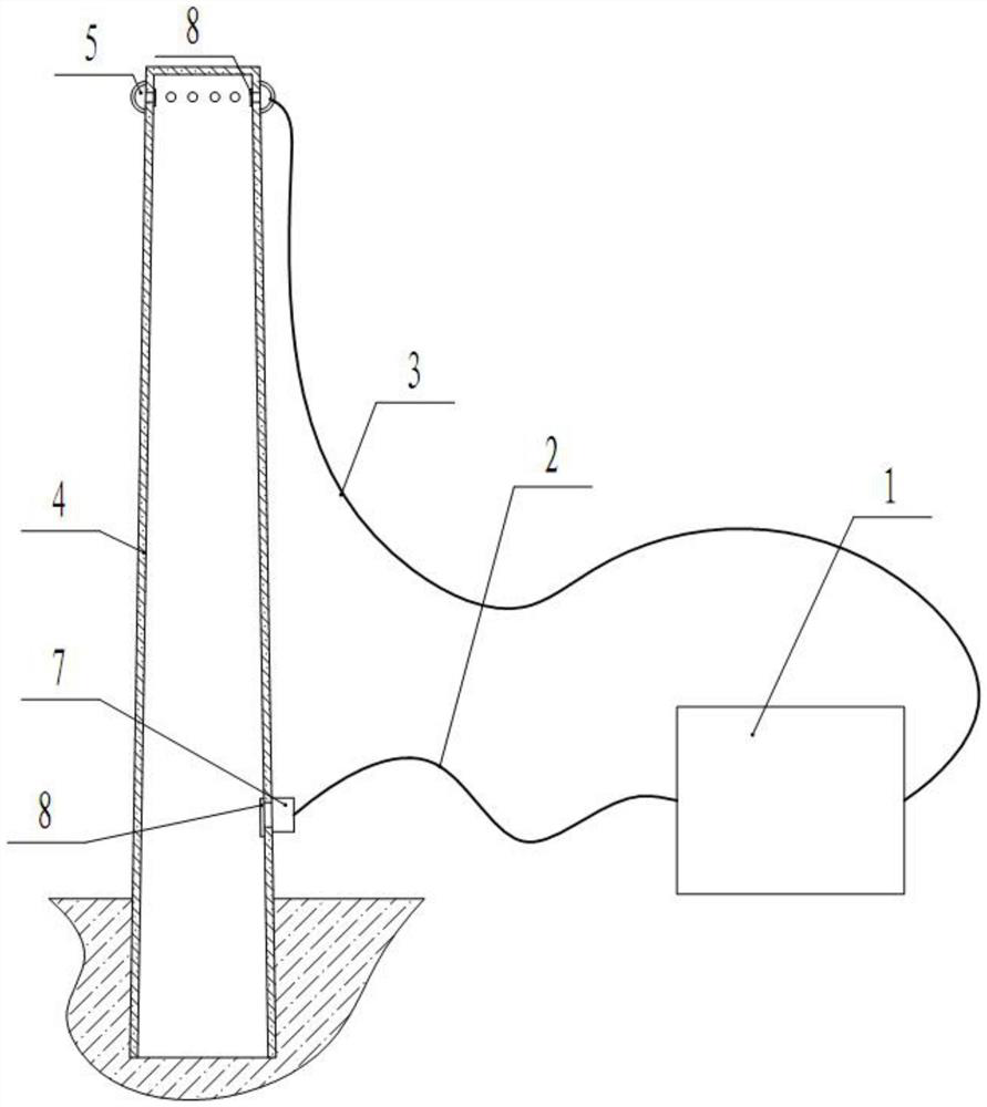
[0020] Embodiment 1: as Figure 1-Figure 2 As shown, a pole hot air deicing device includes a fuel heater 1 and an air inlet pipe 2, the air outlet of the fuel heater 1 is connected to one end of the air inlet pipe 2, and the other end of the air inlet pipe 2 is connected to the bottom of the pole 4. The air inlet is provided with an air outlet around the top of the pole 4. For metal poles, a spiral groove surface can be provided inside to increase the heating contact surface, improve heat transfer efficiency, and facilitate hot air drainage friction to increase heat transfer effect.

[0021] Preferably, the air outlet at the top of the pole 4 and the air inlet at the bottom are provided with metal mesh 8 on the inside to prevent animals and insects from entering and building nests.

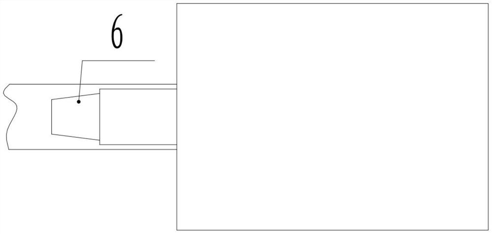
[0022] Preferably, the inner cavity of the electric pole 4 is provided with a heat transfer steel bar, and the heat transfer steel bar protrudes a certain distance from the inner surface of the i...

Embodiment 2

[0028] Embodiment 2: An operation method of a pole hot air deicing device, the method is: connect the air inlet pipe to the joint of the pole and the air outlet of the fuel heater, and connect the circulating air pipe to the fuel heater and the pole At the air outlet of the air outlet, after starting the fuel heater, send warm air to the pole, and control the air supply time. When the set time is reached, or the inside of the ice cube is fused and falls off due to the gravity of the ice cube, stop and clean up. For the ice on the pole, continue to send air until the surface of the pole is dry, and stop sending warm air; the air supply time is determined according to the fusion of ice thickness, external temperature and air supply temperature.


PUM


Abstract

The electric pole hot air deicing device comprises a fuel oil warm air blower and an air inlet pipe, an air outlet of the fuel oil warm air blower is connected with one end of the air inlet pipe, the other end of the air inlet pipe is connected to an air inlet in the bottom end of an electric pole, and air outlets are formed in the periphery of the top end of the electric pole. The electric pole hollow area is small in space, high in heating efficiency and not affected by the external environment. The electric pole is heated from the inside, the surface temperature of the electric pole is increased, the contact surface of ice and the electric pole is melted and falls off, the ice melting effect is better, in addition, heating is continuously conducted after ice melting is finished, and surface accumulated water is rapidly evaporated. When a worker climbs the pole to work, the electric pole can be maintained at a certain comfortable temperature by adjusting the output power of the ice melting device, and the worker is warmed by contacting with the pole body, so that the working environment is improved. Meanwhile, the situation that the friction capacity is reduced due to the fact that the pole climber is hardened at low temperature in winter due to the fact that the friction material is rubber can be improved.

Description

technical field [0001] The invention relates to a pole hot air deicing device and an operating method thereof, belonging to the technical field of pole deicing devices. Background technique [0002] Line icing has always been a major threat to power supply in winter. After the ice disaster in 2008, a large number of excellent results such as DC ice melting technology and ice melting knife gates have appeared in response to line icing. However, there has been no good solution to the icing situation of the poles in the cold area that must be faced in the emergency repair work of the distribution network in winter. The foot buckles of the traditional climbing poles cannot be used, which makes climbing the ice-covered poles a very high safety risk and extremely low operating efficiency. . At present, the following methods are generally used for the climbing work of ice-covered electric poles: [0003] Manual knocking deicing: the efficiency is extremely low, the physical stren...

Claims


Application Information

Patent Timeline
Patent Type & Authority Applications(China)
IPC IPC(8): B08B7/00
CPCB08B7/0071
Inventor 李睿张许齐余洋刘啟磊欧阳柳英高雪颜龙杨吉祥谢薇罗廷杰
Owner GUIZHOU POWER GRID CO LTD
Why Eureka
Try Eureka