Production equipment of fiber reinforced composite pipe

A fiber-reinforced composite and production equipment technology, which is applied in the field of composite pipes, can solve the problems of the difference in shear strength of the pipe performance and the inability to realize the extrusion of continuous fiber composite pipes, and achieve the effect of good bonding effect, high strength and improved strength.

Active Publication Date: 2022-03-18
YONGGAO CO LTD
View PDF11 Cites 1 Cited by
  • Summary
  • Abstract
  • Description
  • Claims
  • Application Information

AI Technical Summary

Problems solved by technology

This mold structure cannot realize the extrusion of continuous fiber composite pipes, but can only mix chopped fibers into hot melt for multi-layer co-extrusion to form multi-layer fiber reinforced composite pipes. Compared with continuous fiber reinforced composite pipes , the pipe performance, especially the difference in shear strength is more obvious

Method used


Image

  • Production equipment of fiber reinforced composite pipe
  • Production equipment of fiber reinforced composite pipe
  • Production equipment of fiber reinforced composite pipe

Examples


Embodiment Construction

[0027] The following is a specific embodiment of the present invention and in conjunction with the accompanying drawings, further describes the technical solution of the present invention, but the present invention is not limited to this embodiment.

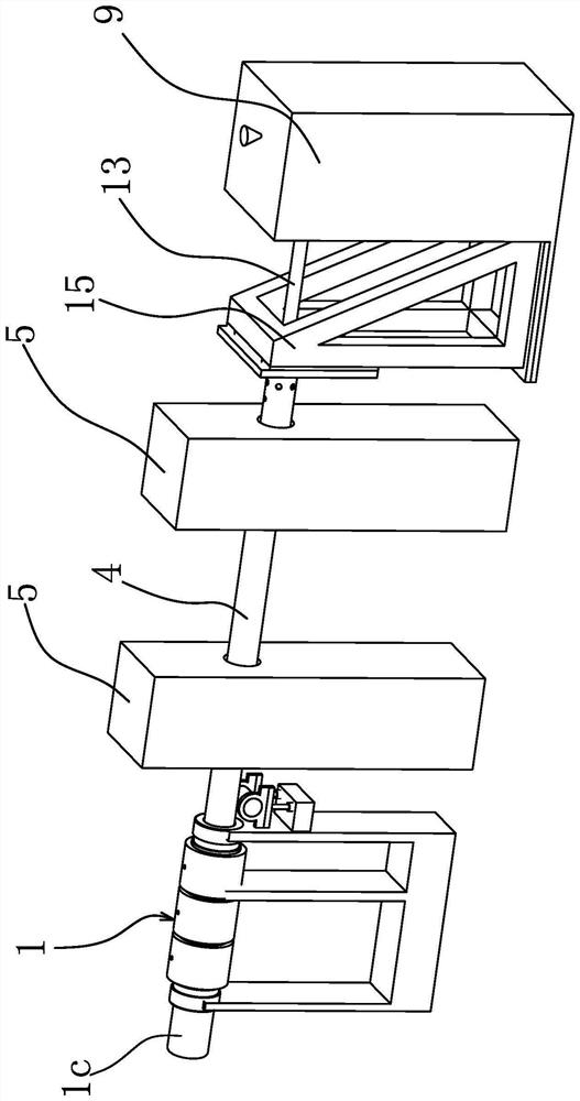
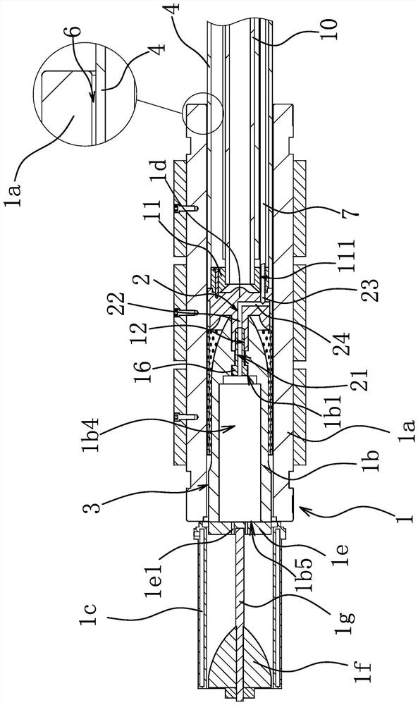
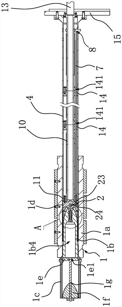
[0028] Such as figure 1 and figure 2 As shown, the production equipment of the fiber-reinforced composite pipe includes a molding die 1, a winding machine 5, an extruder 9, an outer pipe 4 and a core pipe 10 passing through the outer pipe 4, etc., wherein, as figure 2 and image 3 As shown, the molding die 1 includes an outer mold cover 1a, a core mold 1b, a sizing sleeve 1c connected to the outlet end of the outer mold cover 1a, and an air inlet channel 2 communicated with the inner cavity of the sizing sleeve 1c, and the outer mold A molding cavity 3 is formed between the sleeve 1a and the core mold 1b, and the head end of the outer tube 4 and the inlet end of the core tube 10 are both connected to the support frame 15 . T...


PUM


Abstract

The invention provides production equipment of a fiber reinforced composite pipe, and belongs to the technical field of composite pipelines. The problem that in the prior art, a composite pipeline is low in strength is solved. The production equipment of the fiber reinforced composite pipe comprises a forming mold, the forming mold comprises an outer mold sleeve, a core mold, a sizing sleeve connected with the outlet end of the outer mold sleeve and an air inlet channel communicated with an inner cavity of the sizing sleeve, and a forming cavity channel is formed between the outer mold sleeve and the core mold; the production equipment further comprises an outer pipe and a winding machine capable of wrapping the outer peripheral wall of the outer pipe with reinforced fibers, the tail end of the outer pipe extends into the outer die sleeve from the inlet end of the outer die sleeve, an annular cavity channel right opposite to the forming cavity channel is formed between the outer peripheral wall of the outer pipe and the inner peripheral wall of the outer die sleeve, and an air inlet pipe communicated with the air inlet channel is further arranged in the outer pipe. The strength of the fiber reinforced composite pipe can be improved, and meanwhile the stability of the product size is guaranteed.

Description

technical field [0001] The invention belongs to the technical field of composite pipes, and relates to production equipment for fiber-reinforced composite pipes. Background technique [0002] With the continuous expansion of cities and the continuous extraction of oil and natural gas, the demand for transportation pipelines is also increasing. Traditional steel pipes have poor corrosion resistance and are not easy to handle, so they can no longer meet the current needs. Due to its low density, high strength, and excellent mechanical properties, such as good processing performance, good chemical resistance and heat resistance, fiber reinforced composite pipes can still be used stably for a long time in some complex environments. Therefore, it is widely used. [0003] Existing fiber-reinforced composite pipes are mainly continuous fiber-reinforced composite pipes. At present, when continuous fiber-reinforced composite pipes are manufactured, the conventional technology is to...

Claims


Application Information

Patent Timeline
Patent Type & Authority Applications(China)
IPC IPC(8): B29C70/52F16L9/14F16L57/02
CPCB29C70/52B29C70/525B29C70/528B29C70/526F16L9/14F16L57/02
Inventor 陈卫汪鹏跃孙华丽李辉翁志浩李倩
Owner YONGGAO CO LTD
Why Eureka
Try Eureka