


Quick Research
Generate reliable direction feasibility study reports for your R&D in just a few steps.

Technical Q&A
Discover and master advanced knowledge NOW. Basics, ideas, possibilities, all at once.

Find Solutions
As an expert in R&D theories, this can generate solutions to your technical problems instantly.

Evaluate Feasibility
Analyze your overall solution with one click, know your potential R&D risks in advance.

Monitor Landscape
Get weekly tech updates, stay abreast of the latest tech innovations and key insights.
Long-distance tunnel belt conveyor muck discharge energy-saving regulation and control system and regulation and control method
A control system and belt conveyor technology, applied in tunnels, conveyor control devices, conveyors, etc., can solve the problems of high energy consumption and low degree of automation in the ballast step, and achieve the improvement of protection equipment, flexible form, disassembly and assembly. handy effect
- Summary
- Abstract
- Description
- Claims
- Application Information
AI Technical Summary
Problems solved by technology
Method used
Image

Examples
Embodiment 1
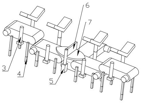
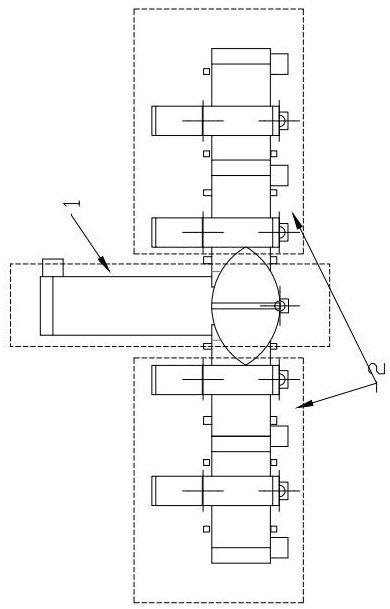
[0036] A long-distance tunnel belt conveyor ballast discharge energy-saving control system and control method, see Figure 1 to Figure 6 , to design a long-distance tunnel belt conveyor ballasting energy-saving control system, including a Y-shaped ballasting transportation chain, wherein the V-head includes two feeding pipe galleries 2 arranged in the main tunnel, and the I-head includes two feed pipes installed in the branch tunnel A ballast discharge pipe gallery 1 in the tunnel, the feed pipe gallery 2 includes at least two belt conveyors 15, and the ballast discharge pipe gallery 1 includes at least one belt conveyor 15, and the above belt conveyors 15 are equipped with infrared sensing mechanisms , the infrared induction mechanism communicates with the control circuit to drive the opening and closing and turning of the power source of the belt conveyor 15; the inflection point is also provided with a shifting block 6 driven by the steering motor 5, and the shifting block 6...
Embodiment 2
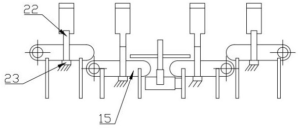
[0048] The working principle of this embodiment is the same as that of Embodiment 1, and the specific difference is that: on the input shaft corresponding to the belt conveyor 15 at the inflection point of the Y-shaped slag-discharging transport chain, a swing mechanism that drives the input shaft to reciprocate is connected. The mechanism includes a four-link 17 mechanism with a power source, wherein on the driving wheel 16 of the swing mechanism, a rocker is formed between the sliding point and the shaft center of the nested installation, and one end of the rocker is connected to the power source. Each end is connected with a rocker and a pendulum, and the inside of the control case 18 is connected with an overrunning clutch 20. The overrunning clutch 20 transmits power only to the input shaft through the intermittent transmission element, and the pivot of the control case 18 forms a pendulum at the connection point with the connecting rod 17. .
[0049] In this embodiment, ...
PUM
 Abstract
Description
Claims
Application Information
 - R&D Engineer
- R&D Manager
- IP Professional
- Industry Leading Data Capabilities
- Powerful AI technology
- Patent DNA Extraction
Browse by: Latest US Patents, China's latest patents, Technical Efficacy Thesaurus, Application Domain, Technology Topic, Popular Technical Reports.
© 2024 PatSnap. All rights reserved.Legal|Privacy policy|Modern Slavery Act Transparency Statement|Sitemap|About US| Contact US: help@patsnap.com