Supporting floating type centrifugal spinning device and using method thereof

A centrifugal spinning, floating technology, applied in textile and papermaking, spinneret assembly, filament/thread forming, etc., can solve the problems of weak dispersion, easy stacking, and finishing loss of centrifugal spinning fibers , to achieve the effect of improving dispersibility, strong dispersibility and high yield

Pending Publication Date: 2022-03-18
WUHAN TEXTILE UNIV
View PDF1 Cites 0 Cited by
  • Summary
  • Abstract
  • Description
  • Claims
  • Application Information

AI Technical Summary

Problems solved by technology

[0004] This design can only produce a single fiber at a time, not only the output is low, but also the centrifugally spun fibers produced have weak dispersion, which leads to easy accumulation after collection, and subsequent finishing will cause losses

Method used


Image

  • Supporting floating type centrifugal spinning device and using method thereof
  • Supporting floating type centrifugal spinning device and using method thereof
  • Supporting floating type centrifugal spinning device and using method thereof

Examples


Embodiment 1

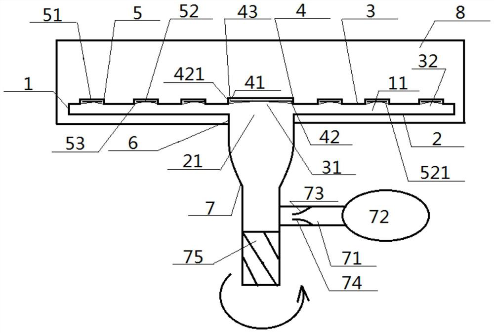
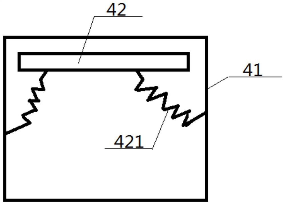
[0054] A floating centrifugal spinning device, comprising a liquid-holding bottom shell 2, a liquid-holding top shell 3, a main nozzle 4 and a plurality of secondary nozzles 5, the periphery of the liquid-holding bottom shell 2 is connected with the liquid-holding shell 1 The periphery of the top shell 3 is connected, and the liquid-holding bottom shell 2, the side enclosure shell 1, and the liquid-holding top shell 3 together form a liquid-holding inner chamber 11, and the middle part of the liquid-holding top shell 3 is provided with a main liquid port 31 and a plurality of The secondary liquid port 32, and the main liquid port 31 is in one-to-one correspondence with the main nozzle 4, and the secondary liquid port 32 is in one-to-one correspondence with the secondary nozzle 5; The bottom of cylinder 41 communicates with liquid-holding cavity 11 through main liquid port 31, and the top of main spray cylinder 41 extends upwards, and the position near its top in main spray cyli...

Embodiment 2

[0057] Basic content is the same as embodiment 1, the difference is:

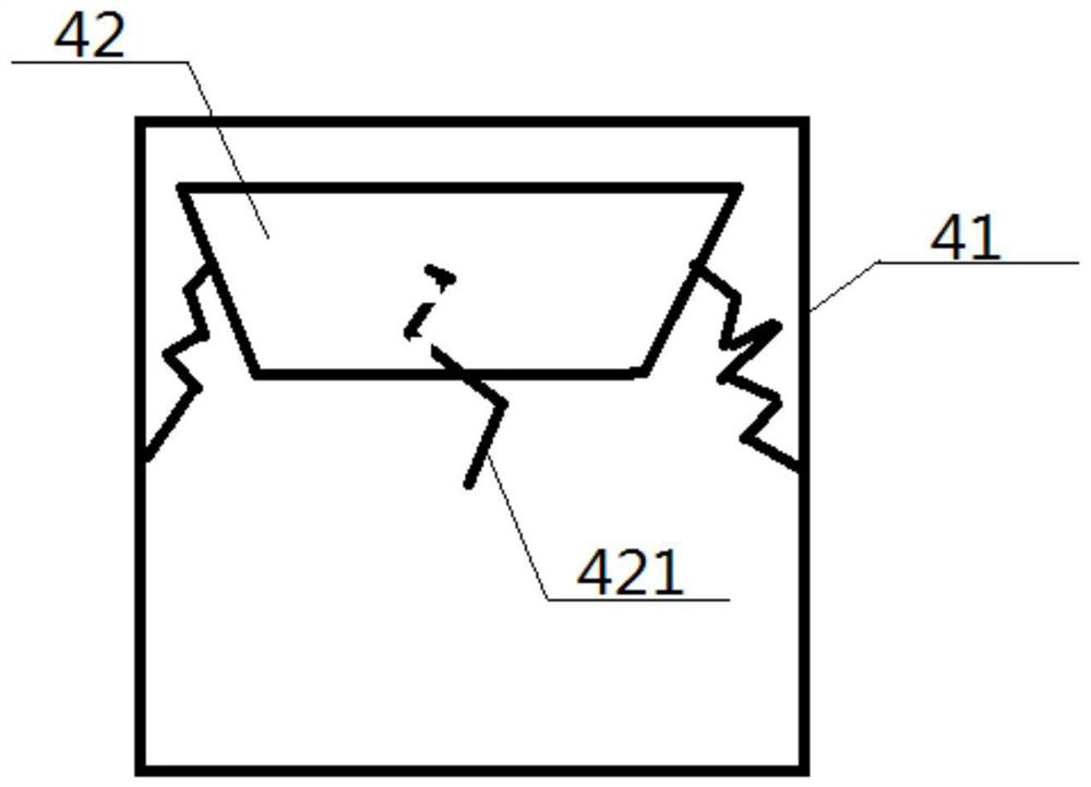
[0058] Both the main support wire 421 and the secondary support wire 521 are made of metal or elastic plastic. Preferably, both the main support wire 421 and the secondary support wire 521 are metal spring wires. Further preferably, both the main floating sheet 42 and the secondary floating sheet 52 are made of metal material or high temperature resistant plastic.

Embodiment 3

[0060] Basic content is the same as embodiment 1, the difference is:

[0061] The main floating plate 42 has the same structure as the secondary floating plate 52, and both include a floating plate bottom plate 44 and a plurality of floating plate nozzles 45 arranged thereon; the floating plate bottom plate 44 is provided with a plurality of floating plate through holes 441, the floating nozzle 45 includes a spray nozzle 451 and a top opening 452 and a bottom opening 453 provided at both ends of the spray nozzle. The middle spray tube 451 communicates with the floating plate through hole 441 through the plate spray bottom opening 453 . The middle tube 451 of the sheet spray is a truncated conical structure with a narrow top and a wide bottom. The area of ​​the top opening 452 of the sheet spray is smaller than the area of ​​the bottom opening 453 of the sheet spray.


PUM


Abstract

A supporting floating type centrifugal spinning device comprises a liquid containing bottom shell, a liquid containing top shell, a main spray head and a plurality of secondary spray heads, a liquid containing inner cavity is defined by the liquid containing bottom shell, a side wall outer shell and the liquid containing top shell, a main liquid opening and a plurality of secondary liquid openings are formed in the middle of the liquid containing top shell, and the main spray head comprises a main spray cylinder and a main floating piece; the bottom end of the main spraying barrel is communicated with the liquid containing inner cavity through a main liquid opening, and an arc-shaped main slit is formed between a main floating piece floating on the portion, close to the top end of the main spraying barrel, in the main spraying barrel and the main spraying barrel; the secondary spray head comprises a secondary spray cylinder and a secondary floating piece, the bottom end of the secondary spray cylinder is communicated with the liquid containing inner cavity through a secondary liquid opening, and an arc-shaped secondary slit is formed between the secondary floating piece floating on the portion, close to the top end, in the secondary spray cylinder and the secondary spray cylinder; the main floating piece is connected with the inner wall of the main spraying barrel through a main supporting wire, and the secondary floating piece is connected with the inner wall of the secondary spraying barrel through a secondary supporting wire. According to the design, the yield is high, dispersity is high, adjustability is high, and the spinning effect is good.

Description

technical field [0001] The invention relates to a centrifugal spinning device, which belongs to the technical field of textiles, in particular to a floating centrifugal spinning device and its use method. Background technique [0002] So far, there are many methods for preparing nanofibers, such as stretching, microphase separation, template synthesis, self-assembly, electrospinning, centrifugal spinning, etc. Among them, the electrospinning method has the advantage of simple operation, but also There are defects such as the need to apply a high-voltage electric field during the preparation process, high cost, additional attention to safety issues, and low production efficiency; while centrifugal spinning refers to the centrifugal force and shear force generated by a polymer melt or solution by means of a high-speed rotating device. Compared with the traditional electrospinning method, centrifugal spinning has higher production efficiency. [0003] The authorized announceme...

Claims


Application Information

Patent Timeline
IPC IPC(8): D01D5/18D01D4/00D01D4/02D01D13/00
CPCD01D5/18D01D4/00D01D4/02D01D13/00Y02P70/62
Inventor 张智明叶沛彦郭庆华刘康徐巧
Owner WUHAN TEXTILE UNIV
Why Eureka
Try Eureka