Flexible connecting device of high-temperature and high-pressure pipeline and using method of flexible connecting device
A connection device and pipeline technology, which is applied to expansion compensation devices, adjustable connections, pipes/pipe joints/pipe fittings for pipelines, etc., can solve the problems of difficult sealing and sealing of non-welded connection pipes, and achieve significant economic benefits and savings. Construction cost, material and space saving effect
- Summary
- Abstract
- Description
- Claims
- Application Information
AI Technical Summary
Problems solved by technology
Method used
Image
Examples
Embodiment 1
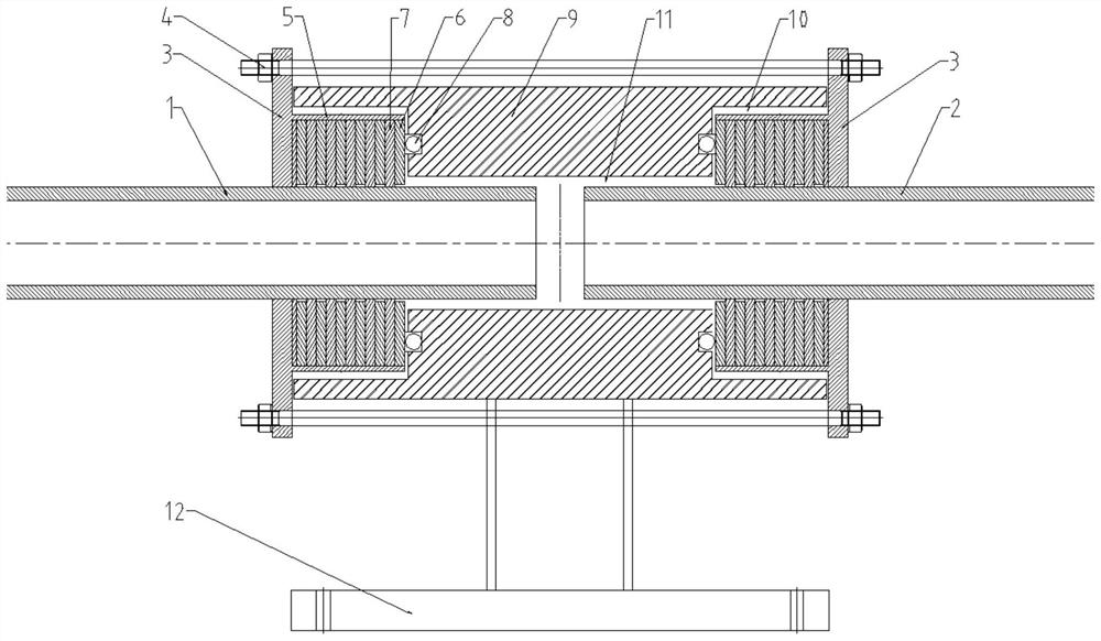
[0038] Such as figure 1As shown, this embodiment provides a pipe connection device, including a first pipe 1 and a second pipe 2, and the first pipe 1 and the second pipe 2 are respectively set on two mounting flanges on the left and right sides. 3, the two mounting flanges 3 are passed through by screw rods, and the screw rods are fastened by mounting bolts and nuts 4, and the mounting bolts and nuts 4 are located on the outside of the mounting flange 3, and the mounting flange 3 has a limiting groove 5 , there is a seal in the limiting groove 5, and there is a cage 9 between the limiting groove 5 and the limiting groove 5, and the cage 9 is in sealing connection with the sealing member, and the cage 9 is located on the mounting flange 3 On the inner side, the first pipe 1 and the second pipe 2 pass through the seal and are located in the holder holder 9 (the end surface contact or butt joint of the first pipe 1 and the second pipe 2 is located in the holder holder 9), so Th...
Embodiment 2
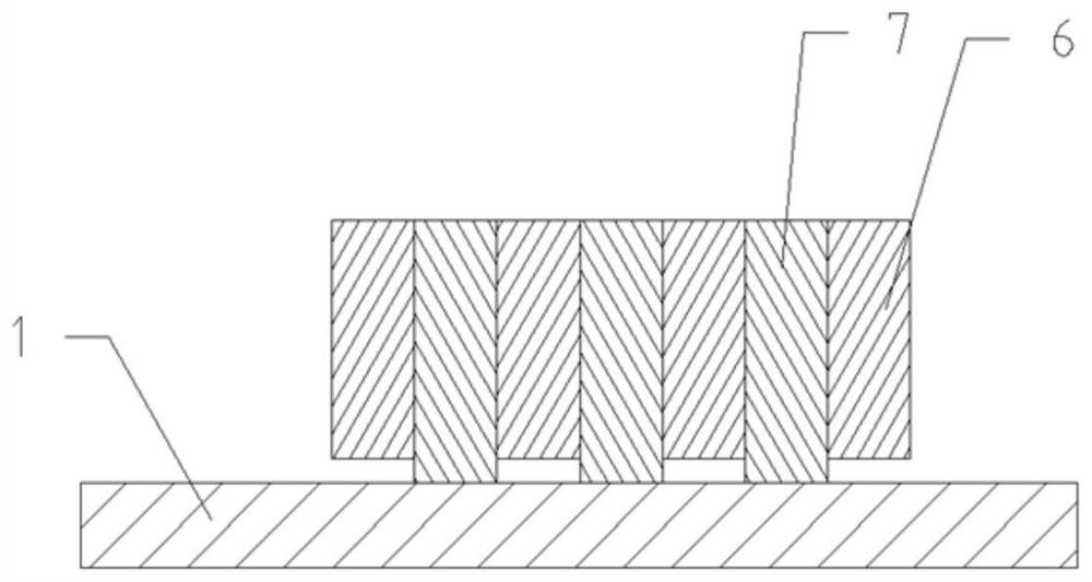
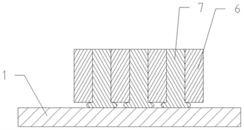
[0044] Such as figure 1 As shown, the quantity of metal sealing gasket 6 and composite molten salt gasket 7 varies with the pressure of the two pipelines. If the pressure is high, a few more layers can be placed, and if the pressure is low, a few layers can be placed. Even if some metal sealing gaskets 6 and composite molten salt gaskets The gasket 7 is located outside the limiting groove 5, and the metal gasket 6 is always in contact with the cage 9 through the metal hollow sealing ring 8 for end-face sealing. Metal hollow sealing ring 8 is made of high-temperature-resistant metal tube, filled with inert gas, and the inert gas expands after being heated, which can ensure the close contact between metal hollow sealing ring 8 and metal gasket 6 to play the role of end face sealing under high temperature. Alternate distribution of metal sealing pads 6 and composite molten salt gaskets 7, under the condition of pressure and constraints on the outer periphery of the two pipes, the...
Embodiment 3
[0047] Although the first pipe 1 and the second pipe 2 are in close contact with the metal sealing gasket 6 and the composite molten salt gasket 7, they can still expand and contract in the axial direction of the first pipe 1 and the second pipe 2, that is, the left, right and left sides can be guaranteed. degrees of freedom to move in the right direction. There is a second movement gap 11 between the first pipe 1, the second pipe 2 and the cage 9, and a first movement gap 10 between the mounting flange 3 and the cage 9, which can ensure the pipes to expand up, down, forward and backward. Time-lapse free movement. The cage 9 is connected to the fixed bracket 12 and remains stationary. The metal hollow sealing ring 8 and the metal gasket 6 are adjusted by adjusting the contact distance between the metal gasket 6 and the cage 9 by adjusting the mounting bolts and nuts 4. The relative displacement between the ring 8 and the metal gasket 6, but can still maintain close contact. ...
PUM
 Abstract
Description
Claims
Application Information
 - R&D
- Intellectual Property
- Life Sciences
- Materials
- Tech Scout
- Unparalleled Data Quality
- Higher Quality Content
- 60% Fewer Hallucinations
Browse by: Latest US Patents, China's latest patents, Technical Efficacy Thesaurus, Application Domain, Technology Topic, Popular Technical Reports.
© 2025 PatSnap. All rights reserved.Legal|Privacy policy|Modern Slavery Act Transparency Statement|Sitemap|About US| Contact US: help@patsnap.com


