Real-time autocorrelator based on radio frequency spectrum conversion and waveform measurement method

A waveform measurement and autocorrelator technology, applied in measurement devices, measuring electrical variables, instruments, etc., can solve the problems of limited autocorrelation waveform measurement rate, limited detection bandwidth of electrical spectrometers and detectors, limited measurement rate, etc. , to achieve the effect of real-time recording of pulse width changes, simplifying the autocorrelation device, and improving the measurement rate

Active Publication Date: 2022-03-18
HUAZHONG UNIV OF SCI & TECH
View PDF11 Cites 0 Cited by
  • Summary
  • Abstract
  • Description
  • Claims
  • Application Information

AI Technical Summary

Problems solved by technology

The traditional radio frequency measurement method is based on the electric spectrometer (ESA) and photodetector (PD), but limited by the detection bandwidth of the electric spectrometer and detector, the general radio spectrum measurement range does not exceed 100GHz, which limits the autocorrelation waveform observation window
[0005]Radio spectrum In addition to electrical measurement methods, optical measurement methods use nonlinear media to load the intensity of radio frequency information to be measured on the phase of pump light, breaking through the electrical bandwidth The measurement bandwidth can reach above THz (Dorrer, Christophe, and D.N.Maywar."RF spectrum analysis of optical signals using nonlinear optics."Journal of lightwave technology 22.1(2004):266.), but the measurement rate is still limited by the spectrum measuring device
The speed-limited radio frequency spectrum measurement system limits the measurement rate of autocorrelation waveforms, which can only reach hundreds of Hz at present

Method used


Image

  • Real-time autocorrelator based on radio frequency spectrum conversion and waveform measurement method
  • Real-time autocorrelator based on radio frequency spectrum conversion and waveform measurement method
  • Real-time autocorrelator based on radio frequency spectrum conversion and waveform measurement method

Examples


Embodiment 1

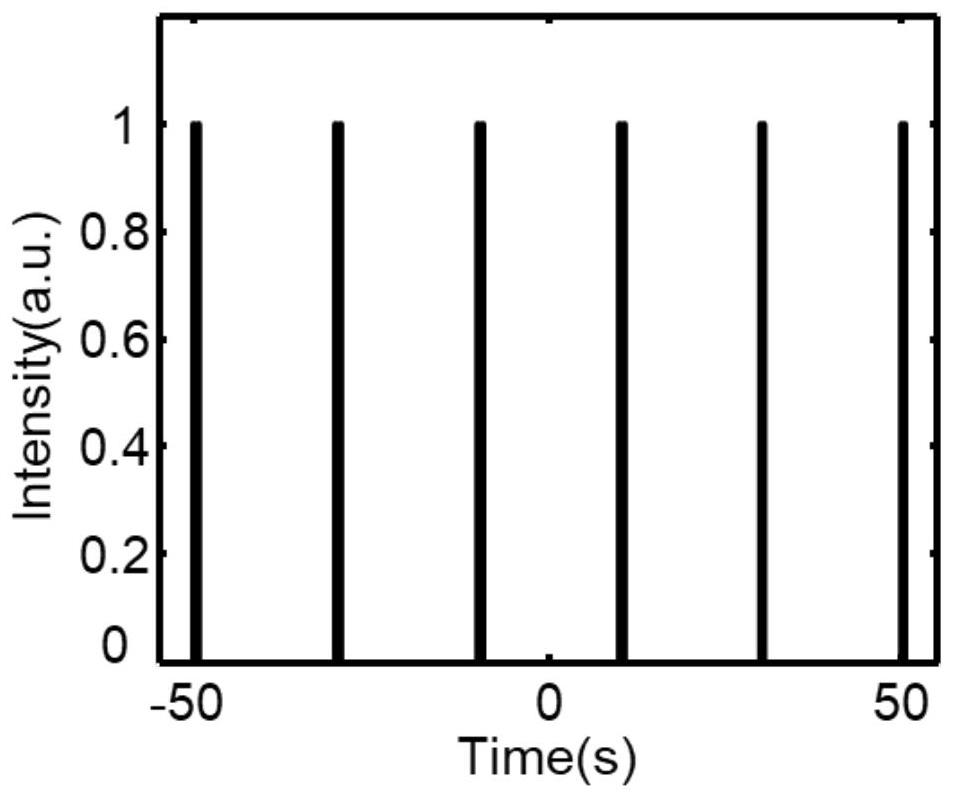
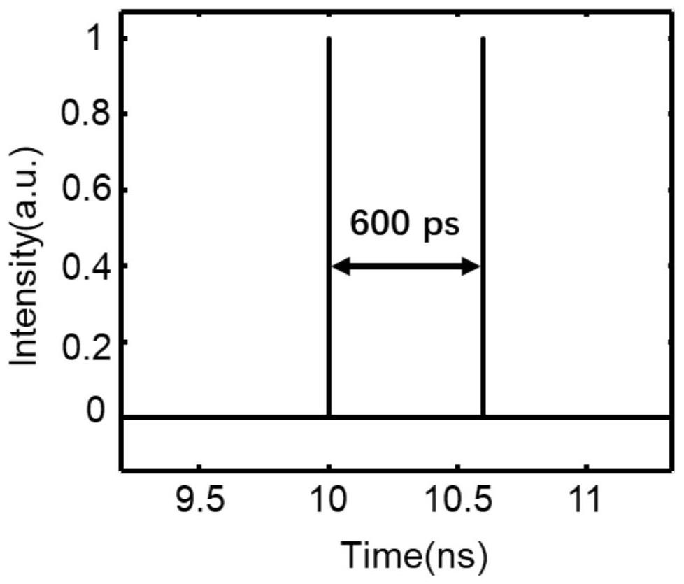
[0097] In order to verify that this program has the characteristics of high speed, large observation window, and high resolution for the measurement of autocorrelation waveforms, this program implements a real-time autocorrelation waveform measurement system with a frame rate of 50MHz, a resolution of 300fs, and an observation window of 600ps. Compared with the traditional autocorrelator, the measurement rate has been increased by 6 orders of magnitude, and the observation window has been increased by an order of magnitude, while the resolution is mainly limited by the measurement bandwidth of the radio frequency spectrum. In this case, a nonlinear waveguide with a nonlinear coefficient of 1w / m is used, so that the 6dB bandwidth of the radio frequency spectrum of the pulse signal is 1THz. In this case, the repetition frequency of the signal to be tested is set to 50MHz, and the pulse width is 250fs. In order to verify the measurement window of the scheme, a double soliton with ...

Embodiment 2

[0110] The observation window, resolution and speed of the real-time autocorrelation system are verified in embodiment 1. In order to verify the performance of the system, in this case, the same pulse width, wavelength setting, dispersion amount and detector detection bandwidth as in embodiment 1 are used , three-solitons and four-solitons with different distances were measured.

[0111] Such as Figure 13 As shown, the time-domain spectra of three solitons with spacings of 150ps and 250ps between pairs within 2ns are given. The pulse width of each soliton is kept at 250fs, and the three pulse intensities are consistent.

[0112] Such as Figure 14 As shown in , the autocorrelation waveform obtained by directly performing autocorrelation operation on the time-domain pulse is given. Since it is three solitons, according to the definition of autocorrelation, the height of the obtained pulse is one-third of the height of the main peak. The time intervals are 150ps, 250ps, and 4...

Embodiment 3

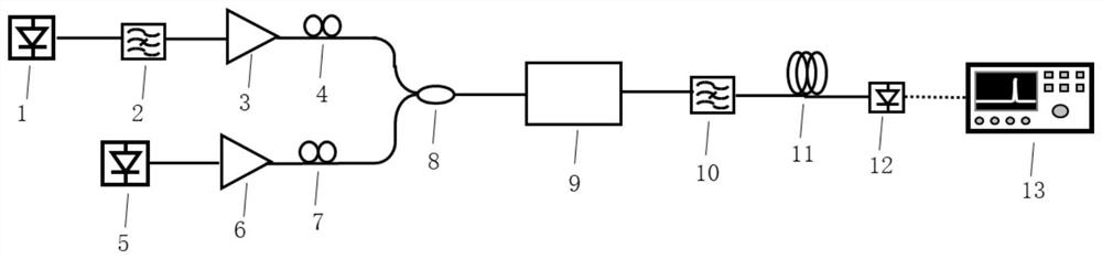
[0115] This embodiment provides a real-time autocorrelation waveform measurement method based on radio frequency spectrum conversion, which mainly includes the following steps:

[0116] Step S1, outputting the pulsed laser as the signal to be measured of the system and the continuous laser as the pumping light;

[0117] Preferably, step S1 also includes filtering and denoising the output pulse laser;

[0118] Step S2, forming a beam of light after coupling the signal to be measured and the pump light;

[0119] Preferably, in step S2, before coupling the signal to be tested and the pumping light to form a beam of light, it further includes performing power amplification on the outputted signal to be tested and the pumping light.

[0120] Preferably, in step S2, before coupling the signal to be measured and the pump light to form a beam of light, it further includes adjusting the polarization states of the signal to be measured and the pump light to keep the polarization states...


PUM

PropertyMeasurementUnit
Center wavelengthaaaaaaaaaa

Abstract

The invention discloses a real-time autocorrelator based on radio frequency spectrum conversion and a waveform measurement method, and belongs to the field of time domain pulse waveform measurement. The method comprises the following steps: S1, respectively outputting pulse laser and continuous laser as a to-be-measured signal and pump light, and coupling the to-be-measured signal and the pump light to form a beam of light; s2, performing cross phase modulation on the coupled light beam, loading radio frequency information of a signal to be measured onto a spectrum of pump light, and obtaining a radio frequency spectrum of the signal to be measured; s3, performing dispersion stretching on the radio frequency spectrum of the signal to be measured to form a radio frequency spectrum mapped to a time domain; and S4, performing photoelectric conversion on the radio frequency spectrum mapped to the time domain to obtain a radio frequency signal, and performing inverse Fourier transform on the radio frequency signal to obtain a pulse autocorrelation waveform which changes in real time. In a word, the method can improve the measurement rate of the real-time self-correlation waveform, and improves the observation window of the self-correlation waveform.

Description

technical field [0001] The invention belongs to the field of time-domain pulse waveform measurement, and more specifically relates to a real-time autocorrelator based on radio frequency spectrum conversion and a waveform measurement method. Background technique [0002] As an instrument for characterizing autocorrelation function in time domain, autocorrelator has the advantages of high resolution, high sensitivity and convenient use, and can measure ultra-narrow pulse width of ps and fs magnitude. [0003] The most commonly used autocorrelator is based on the principle of Michelson interference. The pulse to be measured is divided into two channels through a beam splitter, and one of the signals is scanned by a one-dimensional direction mirror, which brings a delay, and then the two beams with a delay difference Light passing through a nonlinear crystal generates an autocorrelation signal, which converts the time measurement of the pulse into an intensity measurement, which...

Claims


Application Information

Patent Timeline
IPC IPC(8): G01R29/00
CPCG01R29/00
Inventor 陈燎张新亮王若兰胡豪
Owner HUAZHONG UNIV OF SCI & TECH
Why Eureka
Try Eureka