Liquid crystal display device and driving method

A technology of liquid crystal display device and liquid crystal layer, applied in static indicators, nonlinear optics, instruments, etc., can solve the problems of thick cell thickness and low aperture ratio, and achieve the effect of high aperture ratio and reduced cell thickness

Pending Publication Date: 2022-03-18
KUSN INFOVISION OPTOELECTRONICS
View PDF5 Cites 2 Cited by
  • Summary
  • Abstract
  • Description
  • Claims
  • Application Information

AI Technical Summary

Problems solved by technology

[0004] In order to overcome the shortcomings and deficiencies in the prior art, the object of the present invention is to provide a liquid crystal display device and a driving method to solve the problem of the relatively low aperture ratio of reflective display or transmissive display in the prior art and The problem of thick box

Method used


Image

  • Liquid crystal display device and driving method
  • Liquid crystal display device and driving method
  • Liquid crystal display device and driving method

Examples


Embodiment 1

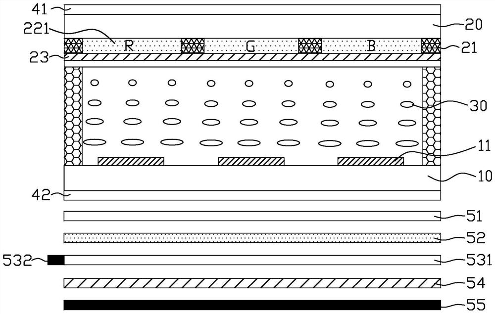
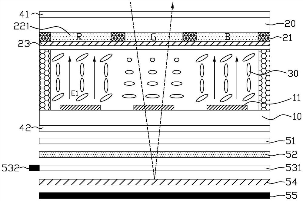
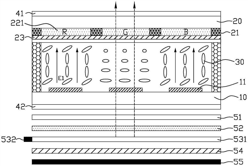
[0037] figure 1 It is a structural schematic diagram of the liquid crystal display device in the initial state in Embodiment 1 of the present invention, figure 2 It is a schematic diagram of the optical path of the liquid crystal display device in the ambient light display mode in Embodiment 1 of the present invention, image 3 It is a schematic diagram of the optical path of the liquid crystal display device in the fill light display mode in Embodiment 1 of the present invention, Figure 4 is one of the planar structural schematic diagrams of the opposite substrate in Embodiment 1 of the present invention, Figure 5 It is the second schematic diagram of the planar structure of the opposite substrate in the first embodiment of the present invention, Figure 6 It is the third schematic diagram of the planar structure of the opposite substrate in the first embodiment of the present invention, Figure 7 It is the fourth schematic diagram of the planar structure of the opposit...

Embodiment 2

[0053] Figure 10 It is a structural schematic diagram of the liquid crystal display device in the initial state in Embodiment 2 of the present invention. Such as Figure 10 As shown, the liquid crystal display device and the driving method provided by Embodiment 2 of the present invention are the same as Embodiment 1 ( Figure 1 to Figure 9 ) in the liquid crystal display device and the driving method are basically the same, the difference is that in this embodiment, the reflective layer 54 is a one-way transflective layer, and the light guide plate 531 is arranged on the side of the reflective layer 54 away from the opposite substrate 20, That is, the reflective layer 54 can not only reflect the ambient light, but also transmit the light emitted from the light guide plate 531 . The unidirectional transflective layer is similar to the window film on a car.

[0054] Further, a phase retardation film 56 is provided between the reflective layer 54 and the light guide plate 53...

Embodiment 3

[0059] Figure 11 It is a schematic structural diagram of the liquid crystal display device in the initial state in Embodiment 3 of the present invention. Such as Figure 11 As shown, the liquid crystal display device and the driving method provided by Embodiment 3 of the present invention are the same as Embodiment 1 ( Figure 1 to Figure 9 ) in the liquid crystal display device and the driving method are basically the same, the difference is that, in this embodiment, the light guide plate 531 is arranged on the opposite substrate 20, by setting the light guide plate 531 on the opposite substrate 20, the supplementary light The light emitted by 532 passes through the liquid crystal layer 30 , is reflected by the reflective layer 54 , and then exits through the liquid crystal layer 30 again, and the light passes through the liquid crystal layer 30 twice. In this way, the optical path difference between the ambient light display mode and the supplementary light display mode i...


PUM


Abstract

The invention discloses a liquid crystal display device and a driving method.The liquid crystal display device comprises an array substrate, an opposite substrate, a liquid crystal layer, a light guide plate, a light supplementing lamp and a reflecting layer, the reflecting layer is arranged on the back face of the array substrate, and a plurality of color resistance areas and a plurality of blank areas are arranged on the opposite substrate; each pixel unit at least corresponds to one color resistance area and/or one blank area, the light supplementing lamp is arranged on the side face of the light guide plate, and the reflecting layer and the light guide plate are both of a whole-face arrangement structure; in the ambient light display mode, the light supplementing lamp is turned off; and turning on the light supplement lamp in the display mode of the light supplement lamp. The whole reflecting layer is arranged and located on the back face of the array substrate, a quarter-wave slide does not need to be arranged, and the box thickness is reduced; the whole pixel unit can realize reflection, and the aperture opening ratio is higher; a light guide plate and a light supplementing lamp are further arranged for light compensation, normal display can be achieved when external environment light is dark, when the light supplementing lamp is used for display, the whole pixel unit can achieve a dark state or a bright state, and the aperture opening ratio is higher.

Description

technical field [0001] The invention relates to the technical field of displays, in particular to a liquid crystal display device and a driving method. Background technique [0002] The display panel has the advantages of thinness, durability, and low power consumption in line with energy conservation and environmental protection. E-paper displays have become a display that meets the needs of the public. E-paper displays can use external light sources to display images, unlike LCD displays that require backlight. Therefore, In an outdoor environment with strong sunlight, the information on the electronic paper can still be seen clearly without the problem of viewing angle, and the electronic paper display has been widely used in electronic reading due to its advantages of power saving, high reflectivity and contrast devices (e.g. e-books, e-newspapers) or other electronic components (e.g. price tags). [0003] Among the existing products, the electronic paper display uses r...

Claims


Application Information

Patent Timeline
Patent Type & Authority Applications(China)
IPC IPC(8): G02F1/13357G09G3/34
CPCG02F1/133605G02F1/133607G02F1/133618G09G3/3406
Inventor 钟德镇廖家德余嘉洺邹忠飞童芬
Owner KUSN INFOVISION OPTOELECTRONICS
Why Eureka
Try Eureka