Design method and device for medium-deep layer buried pipe heat pump heating system

A technology of heating system and design method, applied in hot water central heating system, heating system, geothermal energy and other directions, can solve the problems of difficult system design, low system efficiency, large floor space, etc., and achieve the effect of breaking through technical bottlenecks

Pending Publication Date: 2022-03-18
CHINA ACAD OF BUILDING RES +2
View PDF0 Cites 0 Cited by
  • Summary
  • Abstract
  • Description
  • Claims
  • Application Information

AI Technical Summary

Problems solved by technology

[0006] The original intention of the design of the present invention is that the traditional heating method of replacing coal with electricity has the disadvantages of low system efficiency, poor operation stability, and difficulty in starting of the air source heat pump at low ambient temperature, low heat exchange intensity of the heat exchange system of the shallow buried pipe heat pump, and occupation of land. Large area, the groundwater source heat pump system is difficult to achieve 100% recharge in the same layer, etc. When the existing medium-deep buried pipe geothermal heating system is in operation, the water temperature of the inlet and outlet of the ground side fluctuates greatly, and the medium-deep buried pipe is 2000-3000 There are many formations involved in rice, and the physical parameters of rock and soil are difficult to obtain, which brings great difficulties to the design of the system; for this reason, the scheme provided by the present invention is:

Method used


Image

  • Design method and device for medium-deep layer buried pipe heat pump heating system
  • Design method and device for medium-deep layer buried pipe heat pump heating system
  • Design method and device for medium-deep layer buried pipe heat pump heating system

Examples


Embodiment approach 1

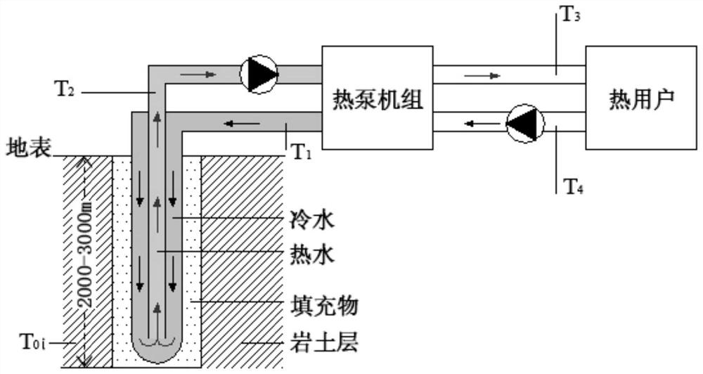
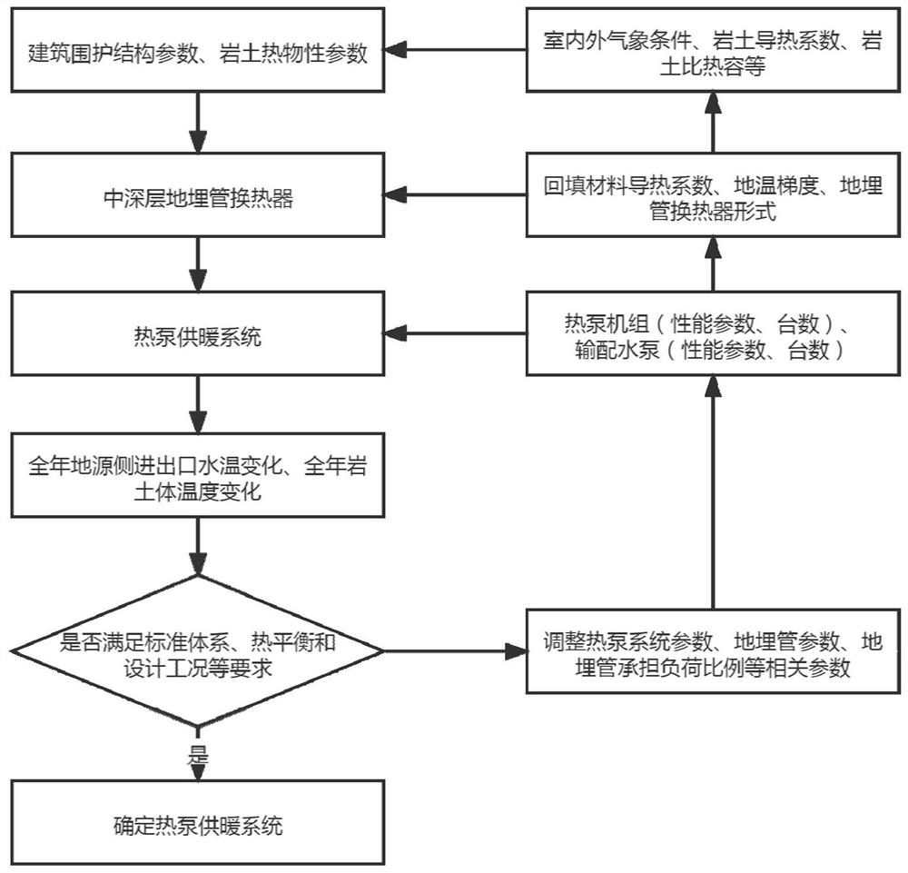
[0065] Implementation Mode 1. Refer to image 3 To illustrate this embodiment, this embodiment provides a design method for a mid-to-deep buried pipe heat pump heating system, and the method includes:

[0066] Building heating load steps for collecting building envelope parameters;

[0067] The geotechnical thermophysical property parameter step of collecting geotechnical thermophysical property parameter;

[0068] According to the collected building envelope parameters and geotechnical thermophysical parameters, the heat exchange steps of medium and deep buried pipes are output to the heat exchange results;

[0069] A step for determining a heat pump heating system based on an output result of the heat exchange step of the medium-deep buried pipe;

[0070] The heat exchange steps of the medium-deep buried pipe are specifically:

[0071] Processing the building envelope parameters and the geotechnical thermophysical property parameters through a heat transfer model;

[007...

Embodiment approach 2

[0083] Implementation mode two, refer to image 3 This embodiment is described. This embodiment is a further limitation of the design method for the mid-deep buried tube heat pump heating system provided in Embodiment 1. The method also includes:

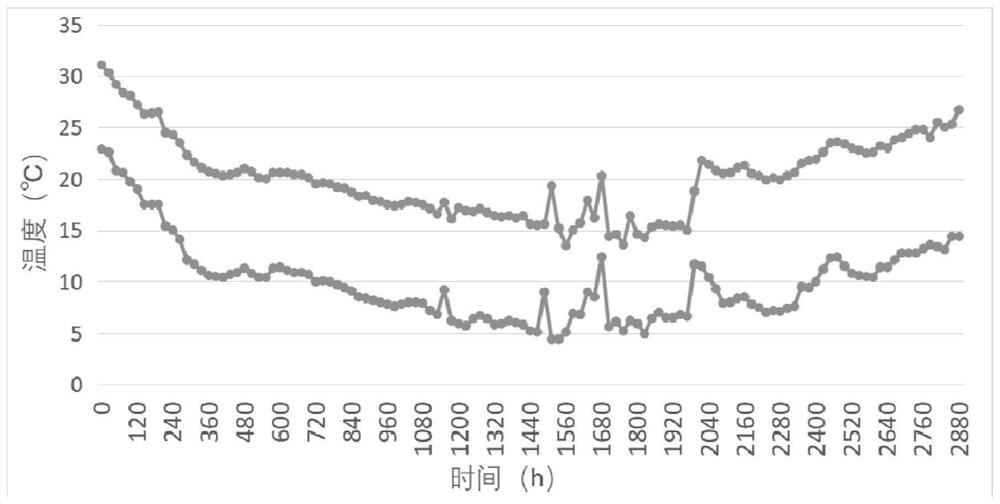
[0084] The water temperature collection step of collecting the water temperature change at the inlet and outlet of the ground source side;

[0085] A temperature collection step for collecting temperature changes of rock and soil mass;

[0086] According to the collected water temperature changes at the inlet and outlet of the ground source side and the temperature changes of the rock and soil mass, the judgment steps of judging whether the requirements of the standard system, heat balance and design conditions are met;

[0087] When the judging result output by the judging module is unsatisfactory, the step of adjusting the parameters in the system is adjusted.

[0088] The benefit of this embodiment is that: the steps of judgmen...

Embodiment approach 3

[0089] Embodiment 3. This embodiment is a further limitation of the design method for the mid-deep buried pipe heat pump heating system provided in Embodiment 1. The initial temperature expression equation of the initial ground temperature in the formation at any depth is:

[0090]

[0091] Among them, t (z) represents the initial temperature of formation at any depth, t a Indicates the surface temperature in °C, q g Indicates the heat flow of the earth, the unit is W / m 2 , h a Indicates the convective heat transfer coefficient between the air and the surface, in W / (m 2 K), k j Indicates the heat transfer coefficient of rock and soil, H j Indicates the coordinates of the bottom of layer j, k m Indicates the heat transfer coefficient of rock and soil, in W / (m 2 K), z represents any depth of rock and soil mass;

[0092] According to the assumption of the heat transfer model, it is considered that the initial temperature distribution is uniform in the radial direction,...


PUM


Abstract

The invention discloses a middle-deep layer buried pipe heat pump heating system design method, and relates to the field of geothermal energy. When an existing medium-deep layer buried pipe geothermal heating system runs, water temperature fluctuation of an inlet and an outlet on the geomarginal side is large, more stratums are involved in 2000-3000 m medium-deep layer buried pipes, physical property parameters of rock-soil bodies are difficult to obtain, and the design of the system is very difficult. Therefore, the scheme provided by the invention is as follows: the design method of the medium-deep layer buried pipe heat pump heating system is realized based on the following devices: a building heating load module for acquiring building envelope parameters; the rock-soil thermophysical parameter module is used for acquiring rock-soil thermophysical parameters; the middle-deep layer buried pipe heat exchanger module is used for outputting a heat exchange result according to the collected building envelope parameters and the rock-soil thermophysical property parameters; determining modules of the heat pump heating system according to the heat exchange structure; the method comprises the following steps: processing building envelope parameters and rock-soil thermophysical parameters through a heat exchange model; the method is suitable for design and reference before construction of a medium-deep layer buried pipe heat pump heating system.

Description

technical field [0001] It relates to the field of geothermal energy, and specifically relates to a design method and device for a heat pump heating system of a medium-deep buried pipe. Background technique [0002] Heating is required in northern areas in winter, and the heating system will cause noise and air pollution. Therefore, "replacing coal with electricity" is the main way to promote clean heating in the north. Heat pump heating is the dominant way of "replacing coal with electricity", and its application area has reached one billion square meters, creating the largest scale in the world. However, there are still low system efficiency, poor operation stability, and difficulty in starting air source heat pumps at low ambient temperatures. Shallow buried pipe heat pump heat exchange system has low heat exchange intensity and large floor area, and it is difficult to achieve 100% same-layer recharge for underground water source heat pump system. [0003] Medium-deep bur...

Claims


Application Information

Patent Timeline
IPC IPC(8): G06F30/13F24D3/18F24T10/17G06F113/08G06F113/14G06F119/08
CPCG06F30/13F24T10/17F24D3/18G06F2113/08G06F2113/14G06F2119/08Y02E10/10Y02B10/40Y02B30/12
Inventor 徐伟李骥孙宗宇杨灵艳李锦堂张广秋薛汇宇
Owner CHINA ACAD OF BUILDING RES
Why Eureka
Try Eureka