Supercharge Your Innovation With Domain-Expert AI Agents!

Optical antenna, optical phased array transmitter and laser radar system

A technology of optical antennas and grating arrays, applied in radio wave measurement systems, optics, optical components, etc., can solve the problems of reduced receiving and data processing accuracy, low light emission efficiency, etc.

Pending Publication Date: 2022-03-18
SUTENG INNOVATION TECH CO LTD
View PDF0 Cites 6 Cited by
  • Summary
  • Abstract
  • Description
  • Claims
  • Application Information

AI Technical Summary

Problems solved by technology

One of the biggest hurdles for OPA LiDAR compared to mechanical LiDAR is that light emission is less efficient and therefore requires higher power; otherwise, the accuracy of reception and data processing is reduced

Method used


Image

  • Optical antenna, optical phased array transmitter and laser radar system
  • Optical antenna, optical phased array transmitter and laser radar system
  • Optical antenna, optical phased array transmitter and laser radar system

Examples


Embodiment Construction

[0020] Reference is now made in detail to the exemplary embodiments, examples of which are illustrated in the accompanying drawings. Wherever possible, the same or like reference numbers will be used throughout the drawings to refer to the same or like parts.

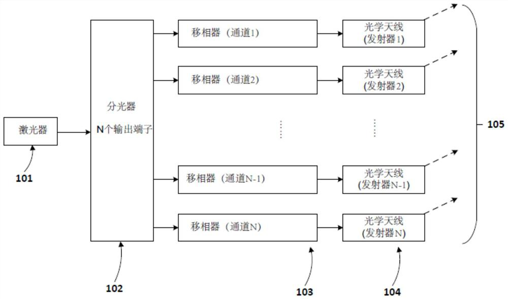
[0021] figure 1 is a schematic diagram of an exemplary OPA transmitter 100 provided by some embodiments of the present invention. The OPA transmitter 100 is a key component of a solid-state lidar system because it can provide phased laser beams to the outside of the lidar system, so that the beams can interfere with each other to form a far-field pattern. Light can be projected onto objects in the environment to be detected. The OPA transmitter 100 in this embodiment may be a PIC manufactured using semiconductor manufacturing technology (eg, CMOS manufacturing technology). A PIC is an integrated circuit that has two or more photonic functions. For example, the OPA transmitter 100 may generate laser light, split the ...


PUM

PropertyMeasurementUnit
Wavelengthaaaaaaaaaa
Pitch rangeaaaaaaaaaa

Abstract

The invention provides an optical antenna (300), an optical phased array transmitter and a laser radar system using the same. The optical antenna (300) includes a substrate constituting at least a portion of a reflective layer (310) having a first material; a waveguide layer (350) disposed over the reflective layer (310) and comprising a second material; and a spacer layer (330) disposed between the waveguide layer (350) and the reflective layer (310) and comprising a third material. The waveguide layer (350) also has a first array of gratings (359). The reflecting layer (310) is used for reflecting light emitted downwards by the waveguide layer (350). The refractive index of the third material is smaller than that of the first material or the second material.

Description

technical field [0001] The present invention relates to an optical antenna, an optical phased array (opatical phased array, referred to as "OPA") transmitter and a lidar system using the above-mentioned device, and in particular to a distance sensing, environmental mapping and Mobile vehicles for obstacle detection. Background technique [0002] Distance sensing and environmental mapping has recently become a hot research area with various uses in industry, for example, it can help security systems detect suspicious approaching objects, and it can also help drones or robots perceive their surroundings, estimate The distance from objects in the environment for avoidance. However, the potential largest and most important application is in the field of autonomous driving, because autonomous driving requires vehicles to be able to sense distances and obstacles (pedestrians, other vehicles, roadblocks, trees, etc.) , to operate the vehicle instead of a human driver. [0003] F...

Claims


Application Information

Patent Timeline
IPC IPC(8): G01S7/481G02B6/12
CPCG01S17/931G01S17/86G01S7/4814G02B6/124G02B2006/12104G02F1/2955G02B27/0087G02B2006/12107
Inventor 汪敬
Owner SUTENG INNOVATION TECH CO LTD
Features
  • R&D
  • Intellectual Property
  • Life Sciences
  • Materials
  • Tech Scout
  • Unparalleled Data Quality
  • Higher Quality Content
  • 60% Fewer Hallucinations
Learn More