
Pile body toughening and monitoring device based on assembly ribs

The technology of monitoring device and pile body is applied in the direction of measuring device, field foundation soil survey, foundation structure test, etc., which can solve the problems of sensor layout difficulty, reduce the layout difficulty, increase the toughness of the pile body, and improve the rigidity of the pile body. and the effect of horizontal resistance

Active Publication Date: 2022-03-22
SHENZHEN UNIV +1
View PDF5 Cites 0 Cited by
  • Summary
  • Abstract
  • Description
  • Claims
  • Application Information

AI Technical Summary

Problems solved by technology

[0004] The purpose of the patent of this invention is to provide a pile body toughening and monitoring device based on assembly ribs. At the same time, the assembly rib increases the contact area between the pile side and the soil, thereby increasing the side friction resistance of the pile, increasing the overall rigidity of the pile body, and improving the bearing capacity and toughening effect of the pile body; the assembly rib is vertically connected by the connecting rod On the one hand, the connection ensures the verticality, and also plays the role of external support; the gasket acts as a hoop through the tightening of the pile body, which improves the compressive performance of the pile body; at the same time, the tensile displacement meter located on the connecting rod can monitor the pile body into the soil Depth; the displacement sensor located on the washer and the pile body can monitor the lateral movement of the pile body; the pressure sensor located on the assembly rib can monitor the surrounding soil pressure; at the same time, the survival rate of the rib can be improved in the form of an assembly rib, and at the same time, it solves the difficulty of sensor layout The problem

Method used


Image

  • Pile body toughening and monitoring device based on assembly ribs
  • Pile body toughening and monitoring device based on assembly ribs

Examples


Embodiment 1

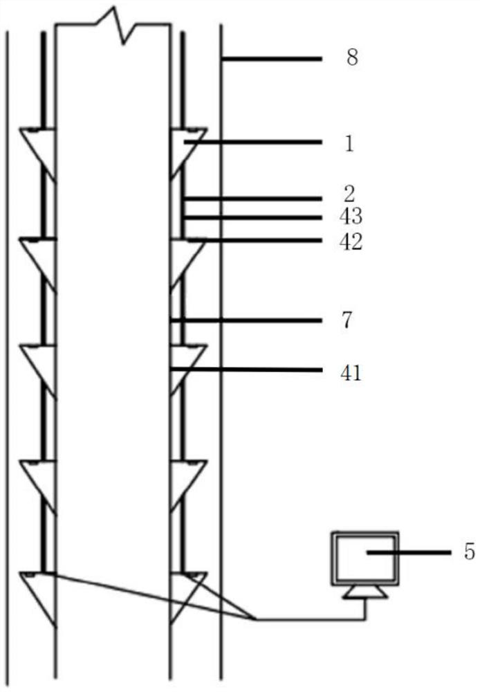
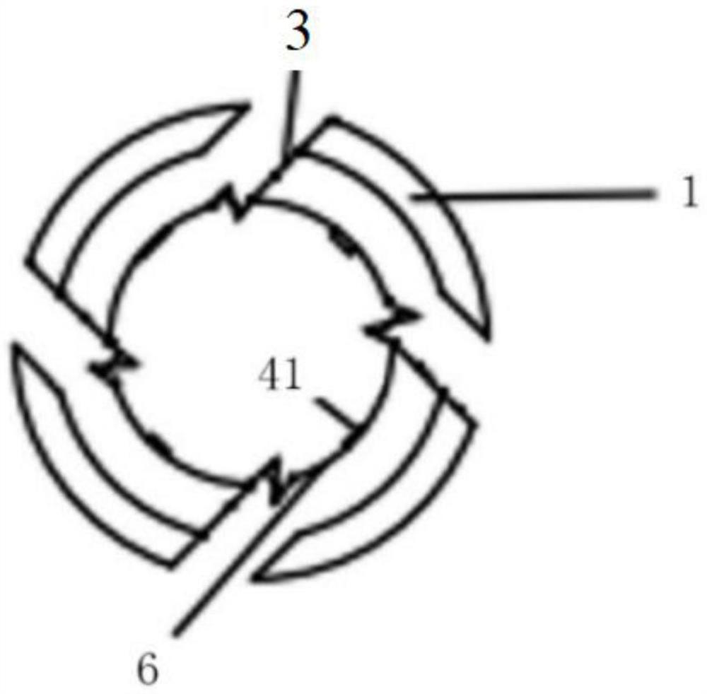
[0025] The two ends of the hinge 3 are respectively connected to the pile body and the assembly rib; the connecting rod 2 is connected to the joint between the assembly rib 1 and the hinge 3 in the same vertical direction; the pile body is equipped with a sensing device 4 to monitor the displacement of the pile body, soil pressure, The depth of the pile body into the soil; the sensing device 4 is electrically connected with the intelligent data acquisition device 5 .

[0026] The inner casing 7, the gasket 6, and the outer casing 8 are arranged sequentially from the inside to the outside, and the gasket 6 is arranged between the inner casing and the assembly rib.

[0027] The displacement sensor 41 is located on the contact surface between the washer 6 and the inner casing 7, and is used for monitoring the displacement of the pile body.

[0028] The pressure sensor 42 is located on the contact surface between the assembly rib 1 and the soil layer, and is used for monitoring th...

Embodiment 2

[0033] The outer casing 7 is to protect the internal structure, in order to ensure that the gasket 6 and the assembly rib 1 are fastened to the inner casing 7, the axes of the inner casing 7, the outer casing 8 and the gasket 6 must coincide;

[0034] Connecting rod 2 will assemble the connection of rib 1 in the same vertical direction;

[0035] The pressure sensor 42 is located on the contact surface between the assembly rib 1 and the soil layer, and is used to monitor the pressure of the soil layer, and is connected with the connecting rod 2, and transmits the data to the intelligent data acquisition device 5;

[0036] The stay wire displacement meter 43 is connected with the connecting rod 2, and is used for monitoring the depth of the pile body into the soil, and transmits the data to the intelligent data acquisition device 5;

[0037] The intelligent data collection device 5 transmits the data collected by the displacement sensor 41 , the pressure sensor 42 , and the wire...

Embodiment 3

[0041] At the beginning, first hollow out and sink into the outer casing 8, and the outer casing 8 plays a protective role for the internal structure;

[0042] Further, first connect the assembly rib 1, the connecting rod 2 and the inner casing 7 on the ground, and simultaneously arrange the displacement sensor 41, the pressure sensor 42 and the wire displacement gauge 43;

[0043] Further, sink the assembled parts and carry out pile construction;

[0044] Further, after the construction of the pile body is completed, the connecting rod 2 is rotated so that the washer 6 is tightly fastened with the pile body, and the installation is completed.

[0045] The pressure sensor 42 is installed on the contact surface between the assembly rib 1 and the soil layer. As the depth of penetration increases, the pressing force of the soil layer on the assembly rib 1 will also increase. The pressure sensor 42 transmits the signal to the intelligent data acquisition device 5 through wires.

...


PUM


Abstract

The invention belongs to the technical field of civil engineering, and relates to an assembly rib-based pile body toughening and displacement monitoring test device, which comprises an outer protective cylinder for fixing an assembly rib, a wedge-shaped assembly rib and a connecting rod for ensuring the perpendicularity of the assembly rib on the wedge-shaped assembly rib, the pressure sensors are arranged on the contact surfaces of the assembling ribs and the pile body; the stay wire displacement meters are arranged on the connecting rods; and an intelligent data acquisition device. The assembling ribs are selected, on one hand, the pulling resistance of the pile can be enhanced, meanwhile, the contact area between the pile side and soil is increased, and the pile side friction resistance is improved; meanwhile, the pile side assembling ribs can play a hoop role, the compression resistance and the horizontal displacement resistance of the pile body are enhanced, and the overall toughness of the pile body is improved; transportation is convenient, and certain engineering significance is achieved; and meanwhile, on-site installation can prevent the rib from being damaged or the sensor from being disturbed during pile pressing. And a scientific and feasible design method is provided for pile body sidesway monitoring.

Description

technical field [0001] The invention relates to the technical field of civil engineering, in particular to a pile body toughening and monitoring device based on assembly ribs. Background technique [0002] Pile is widely used in engineering, and in various forms, it is widely used in various projects. In recent years, in order to make full use of the mechanical properties of materials, piles with special-shaped sections that can increase the side surface area or cross-sectional width of piles have been more and more widely used in practical engineering. For special-shaped piles that change the cross-sectional form of the pile, the external structure may be damaged due to the sinking method of the pile body. At the same time, the layout of the pile sensor is also affected by the pile-forming method and the pile-forming method, so the layout is not easy and has certain difficulties. [0003] Therefore, how to eliminate hidden dangers caused by failure to detect pile damage i...

Claims


Application Information

Patent Timeline
Patent Type & Authority Applications(China)
IPC IPC(8): E02D33/00E02D1/00E02D5/66E02D5/48G01L5/00G01B21/02
CPCE02D33/00E02D1/00E02D5/66E02D5/48G01L5/00G01B21/02
Inventor 包小华程子龙陈湘生刘继强徐世达高星洪源李保军刘宝忠李健刘厚朴张晓东肖云飞朱允伟
Owner SHENZHEN UNIV
Learn More