
A Dynamic Mesh Perturbation Domain Update Method for Simulation of Aircraft Maneuvering Process

A process simulation and update method technology, applied in the field of computational fluid dynamics, can solve problems such as invalid calculation, and achieve the effect of reducing invalid calculation, reducing calculation amount, and improving calculation efficiency

Active Publication Date: 2022-05-10
BEIHANG UNIV
View PDF10 Cites 0 Cited by
  • Summary
  • Abstract
  • Description
  • Claims
  • Application Information

AI Technical Summary

Problems solved by technology

Traditional numerical simulation methods generally use a fixed preset calculation domain to solve dynamic problems, but ignore the feature that "the actual required calculation domain will change with the evolution of the flow field and the convergence of the solution", which may lead to a large number of invalid calculations

Method used


Image

  • A Dynamic Mesh Perturbation Domain Update Method for Simulation of Aircraft Maneuvering Process
  • A Dynamic Mesh Perturbation Domain Update Method for Simulation of Aircraft Maneuvering Process
  • A Dynamic Mesh Perturbation Domain Update Method for Simulation of Aircraft Maneuvering Process

Examples


Embodiment 1

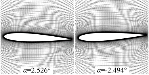
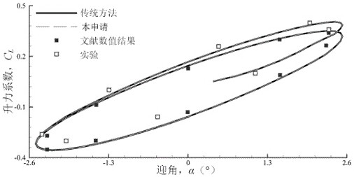
[0183] The method of the invention is used to simulate the pitching motion problem of the NACA0012 airfoil with a Mach number of 0.755. figure 2 Shows the meshes of the present invention simulating the embodiment at the maximum and minimum angle of attack states, where α Indicates the angle of attack. In the figure, due to the pitching motion of the airfoil, the calculation grid coordinates in the numerical simulation also move together with the airfoil. image 3 The lift curve obtained by the present invention is compared with the numerical results of the traditional method and the experimental data of the wind tunnel. Comparison results show that the unsteady aerodynamic results obtained by the present invention are in good agreement with traditional methods and wind tunnel experiments, and the relative aerodynamic deviations are all lower than 10 -3 . Compared with the traditional method, the present invention can shorten the calculation time by 27% due to effectively a...

Embodiment 2

[0185] The method of the invention is used to simulate the pitching motion of a winged missile with a Mach number of 1.58. Figure 4 The aerodynamic coefficients of the winged missile obtained by the present invention and the traditional method are compared. In the figure, the results obtained by the two methods are completely consistent, and the relative deviation of the obtained resistance coefficient is only 10 at most. -5 order of magnitude. Figure 5 Shows the present invention in solving the dynamic domain grid unit amount variation curve in this embodiment; Wherein, n u Represents the ratio of the grid cell volume of the unsteady dynamic domain to the preset computational domain, n c,min Indicates the ratio of the convective dynamic domain to the grid cell volume of the preset computational domain when the inner iteration reaches convergence. In the figure, the scope of the unsteady dynamic domain will change periodically with the pitching motion of the missile; ...


PUM


Abstract

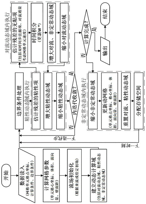
The invention relates to the technical field of computational fluid dynamics, and provides a method for updating a dynamic grid disturbance domain for simulating the maneuvering process of an aircraft. In this method, the influence of grid element velocity and dynamic grid geometry conservation law is considered in the solution of the flow governing equations, and only the unsteady unconverged disturbed elements are solved under the framework of the dynamic grid technology. The solution method of the viscous effect can effectively avoid the invalid calculation of the discrete equation in the traditional numerical simulation method based on the dynamic mesh unit. Secondly, the idea of ​​local updating in the region dominated by unsteady effects is introduced in the update of the coordinates, surface quantities, volumes, and grid unit speeds of the moving grid unit, thereby effectively avoiding the traditional numerical simulation method based on the moving grid unit. Invalid calculation of update grid cell parameters in .

Description

technical field [0001] The invention relates to the field of computational fluid dynamics, in particular to a method for updating a dynamic grid disturbance domain for simulation of an aircraft maneuvering process. Background technique [0002] During the execution of the flight mission, the aircraft needs to continuously adjust the flight attitude through pitch, roll, yaw and other movements, so as to realize the predetermined trajectory flight. When the aircraft adjusts its attitude, flow phenomena such as airflow separation and vortex motion will have unsteady effects caused by the motion of objects, resulting in aerodynamic effects far beyond the prediction of the steady state, and even subversive aerodynamic characteristics that endanger flight safety. Therefore, the prediction of aerodynamic characteristics during aircraft maneuvering is crucial to the design of key subsystems of the aircraft. [0003] Computational fluid dynamics numerical simulation is one of the im...

Claims


Application Information

Patent Timeline
Patent Type & Authority Patents(China)
IPC IPC(8): G06F30/28G06F30/15G06F111/10G06F113/08G06F119/14
CPCG06F30/28G06F30/15G06F2111/10G06F2113/08G06F2119/14Y02T90/00
Inventor 蒋崇文胡姝瑶高振勋许晨豪李椿萱
Owner BEIHANG UNIV
Learn More