
Polarity-variable bus connector for transmitting pulse large current into vacuum chamber

A technology for transmitting pulses and converging polarities, applied in electromagnetic terminals/connectors, climate sustainability, transformers/inductor coils/windings/connections, etc.

Active Publication Date: 2022-03-22
HARBIN INST OF TECH
View PDF3 Cites 4 Cited by
  • Summary
  • Abstract
  • Description
  • Claims
  • Application Information

AI Technical Summary

Problems solved by technology

[0004] The main purpose of the present invention is to solve the problem of reliable connection and insulation between the pulse high current device outside the vacuum chamber and the load coil inside the vacuum chamber in the space plasma environment simulation and research system, so that each pulse high current device The pulse current output by the discharge module can be combined and transmitted to the load coil in the vacuum chamber at the same time to achieve the maximum transmission efficiency of the current
[0005] Another object of the present invention is to solve the problem that the connection between the pulse high current device outside the vacuum chamber and the load coil inside the vacuum chamber should meet the requirements of the vacuum chamber for air tightness, so that the connection has Strong sealing
[0006] Another purpose of the present invention is to solve the problem of how to transfer the heat generated by the load coil inside the vacuum chamber to the outside of the vacuum chamber through the connection of the vacuum chamber wall during the experiment, so as to ensure the normal operation of the load coil

Method used


Image

  • Polarity-variable bus connector for transmitting pulse large current into vacuum chamber
  • Polarity-variable bus connector for transmitting pulse large current into vacuum chamber
  • Polarity-variable bus connector for transmitting pulse large current into vacuum chamber

Examples


specific Embodiment approach 1

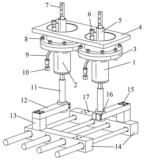
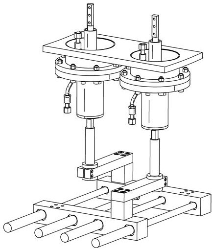
[0032] Specific implementation mode 1, refer to Figures 1 to 3 Describe this embodiment in detail. A variable polarity bus connector for transmitting pulsed large currents to the vacuum chamber described in this embodiment, the bus connector includes a positive terminal 1 and a negative terminal 2 with the same structure and function. , connecting terminal fixing flange 3, ceramic insulating sleeve 5, cabin water pipe ferrule 6, metal conductor 7, terminal fixing flange screw 8, metal water pipe 9, outer water pipe ferrule 10, terminal connecting rod 11, Variable connecting rod 12, transition module 13, bus bar 14, transition module fixing screw 15, clamping screw 16, bus bar fixing screw hole 17.

[0033] The positive terminal 1 and the negative terminal 2 have the same structure and function, and are bridges connecting the load coil in the cabin and the pulse current device outside the cabin.

[0034] The connecting terminal fixing flange 3 is connected with the flange of ...

specific Embodiment approach 2

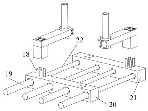
[0044] Specific Embodiment 2. This embodiment is a further description of the variable polarity bus connector that transmits pulsed large currents to the vacuum chamber described in Embodiment 1. In this embodiment, the bus bar 14 includes The outer core bus bar 20, the inner core bus bar 21, and the connecting screw 18. The outer core bus bar 20 and the inner core bus bar 21 are both metal conductors, which are respectively connected to the coaxial cable outer core 19 and the coaxial cable inner core 22, and are used to gather output pulse currents of several discharge modules of the pulse high current device. The number of discharge modules busbar can be extended to access different numbers of coaxial cables.

[0045] The transition module 13 is connected to the outer core bus bar 20 and the inner core bus bar 21 through connecting screws 18, and there are 2 groups in total, 4 pieces in each group. When it is necessary to change the position of the variable connecting rod 1...

specific Embodiment approach 3

[0047] Specific Embodiment 3. This embodiment is a further description of the variable polarity bus connector that transmits pulsed large currents to the vacuum chamber described in Embodiment 1. In this embodiment, the polarity conversion function described It is realized by changing the positions of the variable connecting rod 12 and the transition module 13 . When a group of variable connecting rods 12 and transition modules 13 are connected to the positive terminal 1 and the inner bus bar 21, and another group of variable connecting rods 12 and the transition module 13 are connected to the negative terminal 2 and the outer core bus bar 20, When it is necessary to change the direction of the excitation current provided by the pulse high current device to the load coil, after removing the connecting screw 18, rotate the variable connecting rod 12 connected to the inner core bus bar 21 and the transition module 13 with the terminal connecting rod 11 as the axis 180 degrees, t...


PUM


Abstract

The invention discloses a polarity-variable confluence wire connector for transmitting pulse large current into a vacuum chamber, and relates to the field of pulse power electric energy transmission. Comprising two wiring terminals, a wiring terminal connecting rod, a variable connecting rod, a transition module and a busbar. The wiring terminal is a bridge for connecting a load coil in the vacuum cabin and a pulse current device outside the vacuum cabin; the busbar is used for converging the output current of each discharge module of the pulse large-current device and separating the current outflow end from the current return end of the coaxial cable; and the wiring terminal connecting rod, the variable connecting rod and the transition module are connected with the busbar and the wiring terminal, and are parts for realizing current polarity conversion at the same time. In a vacuum chamber with a relatively high vacuum degree, the confluence wire connector can be used as a connection bridge between a pulse large-current device outside the vacuum chamber and a load coil inside the vacuum chamber; output coaxial cables of all discharge modules of the pulse large-current device outside the vacuum cabin can be connected with input and output ends of a load coil in the vacuum cabin.

Description

technical field [0001] The patent of the present invention relates to the field of pulse power electric energy transmission, specifically a variable polarity bus connector for transmitting high pulse current into a vacuum chamber. Background technique [0002] Space physics involves the study of plasma physics as it occurs in the solar system, and it covers a wide range of scientific topics, including solar activity, physical phenomena of the solar wind, magnetosphere, ionosphere, and thermosphere, and their coupled processes. The ultimate goal of space physics research is to understand solar activity and the basic processes of particle and energy transmission in solar-terrestrial space, and to provide a theoretical basis for predicting space weather, thereby ensuring the normal operation of satellite communications, satellite navigation, and other functions of on-orbit spacecraft. In-situ measurements, usually using high-altitude rockets and satellites, are the main methods...

Claims


Application Information

Patent Timeline
IPC IPC(8): H01R24/00H01R13/02H01R13/40H01R13/502H05H1/24H01F7/06H01F27/28
CPCH01R24/00H01R13/02H01R13/40H01R13/502H05H1/24H01F7/06H01F27/28H01F2007/062Y02E30/10H01R25/16H01F7/202H01F27/29H01R25/00
Inventor 鄂鹏关键金成刚万杰凌文斌朱光亮李立毅
Owner HARBIN INST OF TECH
Learn More