Eureka AIR delivers breakthrough ideas for toughest innovation challenges, trusted by R&D personnel around the world.

Machine room network switch with protection structure

A technology of network switches and protective structures, applied in the field of network switches in computer rooms, can solve the problems that the crystal head and the connection of the crystal head cannot be prevented from falling off at the same time, the maintenance and repair in the post-installation period are not convenient, and the applicability of the installation scene is poor, and the effect of cooling and dust removal is good. , The protective effect is convenient, and the effect of improving the practicability

Inactive Publication Date: 2022-03-22
NANCHANG NORMAL UNIV
View PDF0 Cites 0 Cited by
  • Summary
  • Abstract
  • Description
  • Claims
  • Application Information

AI Technical Summary

Problems solved by technology

[0003] However, as far as the current network switches are concerned, the protection effect is not good, and the applicability of the installation scene is poor. The installation and subsequent maintenance are not convenient enough, and the use efficiency is low. Affects troubleshooting efficiency, cannot achieve full-scale dust removal and cooling, and affects service life

Method used


Image

  • Machine room network switch with protection structure
  • Machine room network switch with protection structure
  • Machine room network switch with protection structure

Examples


Embodiment

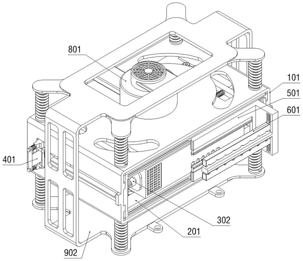
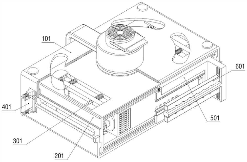
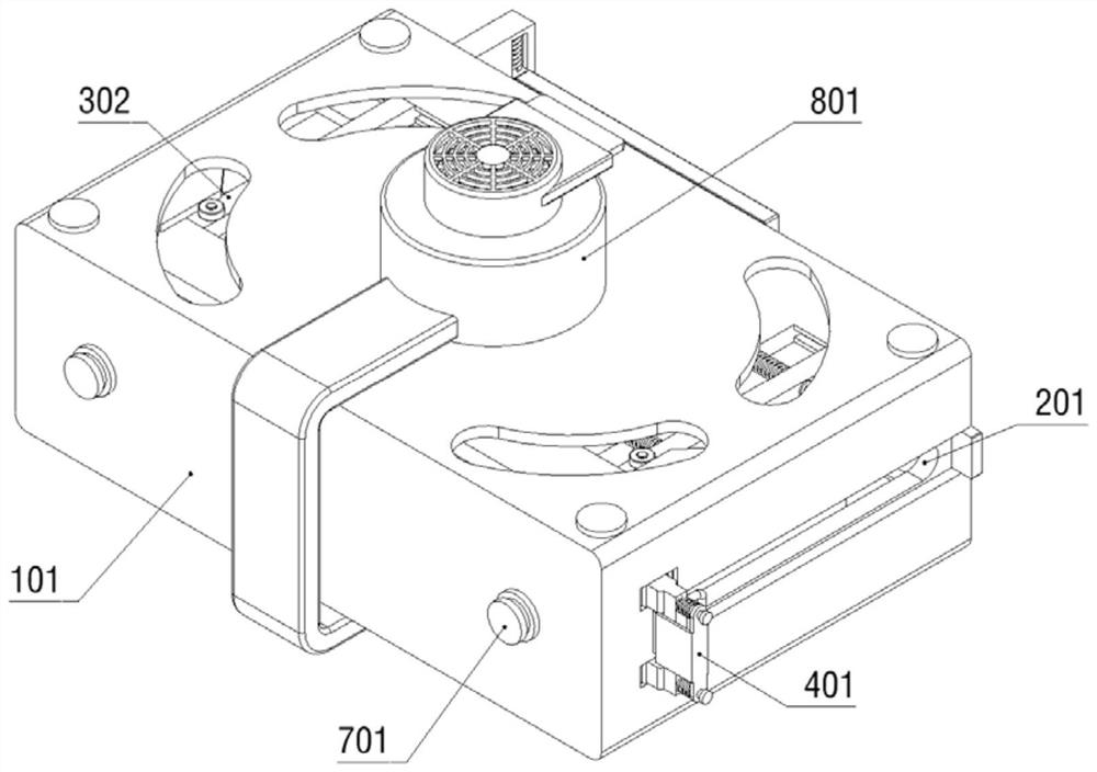
[0038] Example: Please refer to Figure 1 to Figure 12 :

[0039] The present invention proposes a computer room network switch with a protective structure, which includes an installation shell 1; a telescopic part 2 is slidably connected to the installation shell 1; linkage positioning devices 3 are respectively installed on both sides of the telescopic part 2; the sides of the telescopic part 2 are fixed The one-way positioning part 4 is connected; the front side of the telescopic part 2 is slidingly connected with the anti-off device 5; the anti-off device 5 is fixedly connected with the wire harness positioning part 6; the rear side of the installation shell 1 is slidingly connected with two opposite extrusions Part 7; the installation shell 1 is fixedly connected with a two-way cooling device 8; the outside of the installation shell 1 is fixedly connected with an elastic support part 9; the installation shell 1 includes: an installation shell 101, and two spines are fixed...


PUM


Abstract

The invention provides a machine room network switch with a protection structure, and relates to the technical field of paint spraying, and the machine room network switch comprises an installation housing which is in sliding connection with a telescopic part; linkage positioning devices are mounted on the two sides of the telescopic part respectively; the side surface of the telescopic part is fixedly connected with a one-way positioning part; the front side of the telescopic part is slidably connected with an anti-disengaging device. The anti-falling device is fixedly connected with a wire harness positioning part; two opposite extrusion pieces are slidably connected to the rear side of the mounting shell; the installation shell is fixedly connected with a bidirectional heat dissipation device, the overall cooling and dust removal effects are better, wire ends are inserted more firmly, wire harnesses are more standard, the stability of follow-up use of equipment is overall improved, and the problems that for an existing network switch, the protection effect is poor, the applicability to installation scenes is poor, installation and later maintenance are not convenient enough, and the service life is long are solved. And the problems that the crystal head and the crystal head wiring cannot be simultaneously prevented from falling off, and full-range dust removal and cooling cannot be realized are solved.

Description

technical field [0001] The invention relates to the technical field of network switches, in particular to a computer room network switch with a protective structure. Background technique [0002] Network switches play an important role in all walks of life. It can provide an exclusive electrical signal path for any two network nodes connected to the switch. Because it involves network experience and other issues, a good one with protection Structured computer room network switches are particularly important in different installation scenarios. [0003] However, as far as the current network switches are concerned, the protection effect is not good, and the applicability of the installation scene is poor. The installation and subsequent maintenance are not convenient enough, and the use efficiency is low. It affects the efficiency of troubleshooting, cannot achieve full-scale dust removal and cooling, and affects the service life. Contents of the invention [0004] In vie...

Claims


Application Information

Patent Timeline
Patent Type & Authority Applications(China)
IPC IPC(8): H04L49/10H04Q1/02H04Q1/06H05K7/20H01R13/639
CPCH04L49/10H04Q1/035H04Q1/06H01R13/639H05K7/20172H05K7/20145H05K7/20181
Inventor 刘旺勤
Owner NANCHANG NORMAL UNIV
Why Eureka
Eureka Blog
Learn More