[0040] The present invention will be further described below in conjunction with the accompanying drawings.
[0041] refer to Figure 1 to Figure 9 , a method for drilling and preparing holes for an oral implant robot based on real-time temperature perception, comprising the following steps:
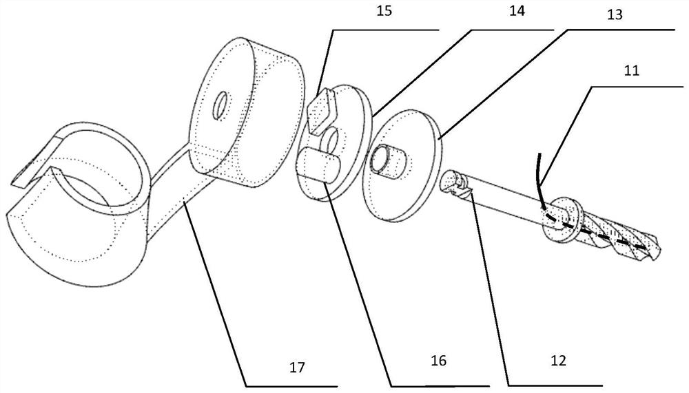
[0042] 1) Temperature sensing drill selection
[0043] According to the implant model in the implant plan, the diameter and length of the temperature-sensing burs are selected, and the temperature-sensing burs with different diameters will affect the heating rate of the heat source in the temperature field model;
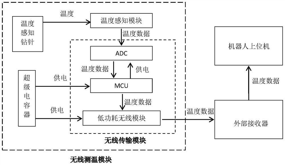
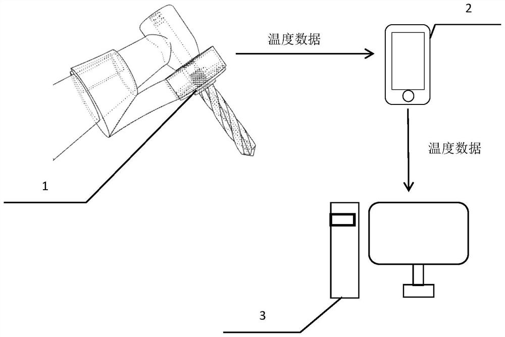
[0044] 2) Wireless temperature measurement module installation
[0045] Install the wireless temperature measurement module on the planting phone and check the stability of the connection;
[0046] 3) Transmission test of wireless temperature measurement module
[0047] Power on the wireless temperature measurement module before preparing the hole, and start the planting phone to rotate at the set speed. The wireless temperature measurement module sends the temperature in real time according to a certain frequency to sense the internal temperature of the drill, and the external receiver starts to receive the temperature data. Test the stability of data transmission and whether the data format is correct, and store it in the information storage module. After the data reception test is completed without any problems, the robot-assisted surgery can be performed;
[0048] 4) Adaptive control of motion parameters during hole preparation
[0049] When the hole preparation operation starts, the host computer obtains temperature data, and calculates the highest temperature T in the bone tissue according to the temperature field model Q(s,t). max , and calculate the temperature rise rate T according to the temperature rise rate model ir , and add it to the temperature adaptive parameter control model T c;
[0050] The motion parameter control cycle in the process is as follows:
[0051] First select the mode with or without cooling water:
[0052] 4.1) With cooling water mode: the wireless temperature measurement module continuously obtains the temperature measurement point data, and the host computer infers the highest point temperature and temperature rise rate of the bone temperature according to the temperature data, and judges whether the highest point temperature and temperature rise rate are adaptive to the temperature. Within the safe range of the parameter control model, if they are all within the safe range, the speed can be increased to 1000-1200rpm, and the feed rate can be increased to 0.6-1mm/s to speed up the hole preparation speed; if it exceeds, judge whether the temperature reaches the warning temperature. If the temperature is lower than the warning temperature in the temperature adaptive parameter control model but the temperature rise rate exceeds the temperature rise rate threshold, reduce the feed speed to 0.3-0.6mm/s, adjust the speed to 800-1000rpm, and increase the cooling water flow rate to full speed In order to reduce the temperature rise rate, if the temperature reaches the warning temperature, the drill needle is pulled up and the cooling water flow rate is increased to the full speed to cool down. During the process, it is judged whether the hole preparation is completed. If the drilling preparation is completed, the process ends;
[0053] 4.2. No cooling water mode: No cooling water is used in the process, the wireless temperature measurement module continuously obtains the temperature measurement point data, and the upper computer infers the highest point temperature and temperature rise rate of the bone temperature according to the temperature data, and judges the highest point temperature and temperature. Whether the rise rate is within the safe range of the temperature adaptive parameter control model, if it is within the safe range, the speed can be increased to 1000-1100rpm, and the feed rate can be adjusted to 0.5-0.8mm/s to speed up the hole preparation speed; Then judge whether the temperature reaches the warning temperature. If the temperature does not reach the warning temperature in the temperature adaptive parameter control model but the temperature rise rate exceeds the threshold, reduce the feed speed to 0.2-0.5mm/s, and adjust the rotation speed to the range of 800-1000rpm to reduce the temperature. If the temperature exceeds the warning temperature, the drill needle is pulled to cool down; in the process, it is judged whether the preparation of the hole is completed, and if the preparation of the hole is completed, the process ends.
[0054] The specific parameters in the above process are obtained by inputting the temperature data into the temperature adaptive parameter control model for calculation.
[0055] In the above process, the preparation of the implant cavity is completed with one drilling. If tapping is required, use a thread forming drill to form the desired thread shape on the inner wall of the implant cavity.
[0056] 5) After the process is over, remove the wireless temperature measurement module from the planting phone and carry out disinfection.
[0057] Further, in the step 4), the hole preparation temperature field model Q(s, t): the hole preparation temperature field model reflects the temperature change of the drill needle and each point in the alveolar bone over time during the hole preparation process, The parameters include position s, time t, heat transfer rate and heat source heating rate. According to the temperature of one point in the temperature field, the temperature of other positions in the temperature field is calculated, and the corresponding transmission rate is modified according to the temperature sensing drill of different types. The thermal parameters and the heating rate of the heat source, using the temperature field model, calculate the temperature at the highest temperature in the bone tissue according to the temperature at the position measured by the sensor in the temperature sensing drill in the wireless temperature measurement module to obtain the highest temperature T in the bone tissue max.
[0058] Further, in the step 4), the temperature rise rate model T ir (n, v, q, T(t)): The temperature rise rate model reflects the change trend of temperature in a short time. When the temperature rises, the temperature rise rate is positive, and when the temperature drops, the temperature rise rate is negative. Speed v and T ir is a positive correlation, the cooling water flow rate q and the temperature rise rate T ir is a negative correlation, use the temperature rise rate model to calculate the current temperature rise rate, and then calculate the temperature situation in a short time.
[0059] Further, in the step 4), the temperature adaptive parameter regulation model T c (n,v,q,T(t),T ir ,T w ): The temperature adaptive parameter control model reflects the relationship between drill speed, feed rate, cooling water flow rate and temperature change. By inputting real-time temperature T(t), temperature rise rate T ir with the warning temperature T w Obtain robot motion parameters: drill speed n, feed speed v, cooling water flow rate q. According to the real-time temperature T(t), the temperature rise rate T ir with the warning temperature T w Dynamically adjust the motion of the robot to achieve a balance between temperature control and efficiency.
[0060] The one-drill hole preparation technique in this embodiment refers to the preparation of an implant cavity with only one drill by selecting a drill with an appropriate diameter on the basis of controlling the maximum temperature in the alveolar bone. The key lies in the robot-assisted surgery. During the process, the temperature measurement near the surgical site of the patient's alveolar bone and the use of an adaptive parameter model to achieve the control of the highest temperature in the bone tissue during the hole preparation process.
[0061] In the step 2), the wireless temperature measurement module 1 includes a temperature sensing module 11, a temperature sensing drill 12, an internal connector 13, a PCB board 14, a wireless transmission module 15, a power module 16 and an external protective shell 17, so The temperature sensing module 11 is located in the temperature sensing drill 12, the internal connector 13 is sleeved on the temperature sensing drill 12, the PCB board 14 is connected with the internal connector 13, and the wireless transmission module 15 and The power supply module 16, the internal connector 13, the PCB board 14, the wireless transmission module 15, and the power supply module 16 are all located in the outer protective shell 17; the temperature sensing module 11 is connected to the wireless transmission module 15, and the wireless transmission module 15 Both are connected to the power module 16 .
[0062] The wireless temperature measurement module 1 is connected to an external receiver 2 , and the external receiver 2 is connected to the robot host computer 3 .
[0063] Further, the temperature sensing module 11 is a thermocouple or other temperature sensor.
[0064] The wireless transmission module 15 includes an ADC and an MCU, the ADC is used to convert the analog quantity into a digital quantity and send it to the MCU, and the MCU realizes the reading of the ADC data according to a certain frequency and controls the external data flow of the wireless transmission module. transmission.
[0065] The power module 16 uses a super capacitor.
[0066] The external receiver 2 is used to receive the data sent by the wireless module, and send the temperature data to the robot host computer, using a mobile phone or other devices that can be used for wireless connection.
[0067] The robot host computer is used for analyzing and processing the temperature data after receiving the temperature data, and generating corresponding robot motion parameters based on the temperature data.
[0068] The wireless transmission module 15 also includes a low-power wireless module, which implements the external transmission of data streams.
[0069] The temperature sensing drill needle 12 is used for drilling, and has a hole inside for accommodating the temperature sensing module 11 .
[0070] The data transmission path of this embodiment: the sensing end of the temperature sensing module is installed inside the temperature sensing drill, the other end is connected to the ADC, the ADC converts the analog quantity into digital quantity and transmits it to the MCU, and the MCU transmits the data stream to the wireless transmission module, The wireless transmission module transmits the data stream to the external wireless receiver.
[0071] The system operation process of this embodiment: after the wireless temperature measurement module is powered on, it is only used as a slave, and continuously transmits real-time temperature data according to a certain frequency. After the external receiver is wirelessly connected to the slave, the temperature data is received in real time and sent to The robot host computer, the host computer analyzes and processes the temperature data, generates robot motion parameters, and sends the motion parameters to the robot side.
[0072] like figure 1 As shown, the wireless temperature measurement system as a whole includes the following modules: temperature sensing module: thermocouple or other temperature sensor; PCB board; wireless transmission module, power module: super capacitor; Protective case; external receiver: mobile phone or other device that can be used for wireless connection; robot host computer.
[0073] A temperature sensing module 11, a temperature sensing drill 12, an internal connector 13, a PCB board 14, a wireless transmission module 15, a power supply module 16 and an external protective shell 17, the temperature sensing module 11 is located in the temperature sensing drill 12, the The internal connector 13 is sleeved on the temperature sensing drill 12, the PCB board 14 is connected with the internal connector 13, the wireless transmission module 15 and the power module 16 are installed on the P internal connector, the internal connector 13, the PCB board 14 , the wireless transmission module 15 and the power supply module 16 are located in the external protective shell 17;
[0074] The temperature sensing module 11 is connected to the PCB board 14 , the PCB board 14 is connected to the wireless transmission module 15 , and both the PCB board 14 and the wireless transmission module 15 are connected to the power supply module 16 .
[0075] The data exchange path is: the temperature sensing end of the temperature sensing module is installed inside the temperature sensing drill, and the other end is connected to the ADC. The module sends the data stream to the external receiver, and the external receiver transmits the data to the robot host computer.
[0076] like figure 2 As shown in the figure, the intraoperative wireless temperature measurement module is integrally installed on the planting mobile phone. After collecting the temperature data, the temperature data is sent to the external receiver, and the external receiver transmits the data to the robot host computer.
[0077] like image 3 Shown is an exploded view of the structure of the wireless temperature measurement module, which includes the following modules: temperature sensing module: thermocouple or other temperature sensor; ADC; MCU module; low-power wireless module; power module: super capacitor; temperature sensing drill; structure pieces.
[0078] The ADC, MCU, and low-power wireless modules are integrated into a wireless transmission module as shown in the figure. The wireless transmission module and the power module are mounted on a ring-shaped PCB. There is a hole in the middle of the PCB board to connect the internal connector, and the internal connector is mounted on the temperature sensing drill pin through the thread.
[0079] The outer protective shell is covered on the outside to isolate the internal electronic components from the external environment, but the outer protective shell is not in contact with 1 to 6, and one end of the outer protective shell is installed on the planting mobile phone.
[0080] One end of the temperature sensing module is buried inside the temperature sensing drill pin, and the other end extends through the small hole on the temperature sensing drill pin and is connected to the PCB board.
[0081] like Figure 4 Shown is a cross-sectional schematic diagram of the temperature sensing drill, which has a hole inside for inserting the temperature sensing module. There are threads on the periphery for connecting internal connectors.
[0082] like Figure 5 The schematic diagram of the temperature field model is shown. The end of the temperature sensing module is the temperature measurement point. The contact position between the drill needle and the alveolar bone is the heat source. The relationship between the temperature measurement point and the drill tip is known. According to the temperature at the temperature measurement point, the drill tip can be inferred. The temperature of the drill tip is in contact with the alveolar bone, and the temperature change at the highest temperature in the alveolar bone is deduced.
[0083] like Image 6 Shown is the operation flow chart of a drilling preparation technique. The operation process is as follows: 1. Preoperative plan planning; 2. Select appropriate temperature sensing probe; 3. Install wireless temperature measurement module; 4. Data transmission test, if the signal transmission is stable Continue the follow-up process. If the transmission is unstable, check the cause, replace the wireless temperature measurement module, and repeat steps 3 and 4; 5. After passing the data transmission test, prepare for hole preparation; 6. Carry out adaptive parameter control during hole preparation to achieve 1. Drill the prepared hole; 7. After the preparation of the hole, remove the wireless temperature measurement module and carry out disinfection.
[0084] like Figure 7 The flow chart of adaptive parameter control is shown in the figure. The cycle in the process is as follows: first select the mode with or without cooling water, then adjust the robot motion parameters according to the corresponding mode, and check whether the hole preparation has been completed during the process. Completion will end the temperature adaptive parameter control.
[0085] like Figure 8 Shown is the flow chart of adaptive parameter control with cooling water mode. The cycle is as follows: the wireless temperature measurement module continuously obtains the temperature measurement point data, and the host computer infers the highest point temperature and temperature rise rate of the bone temperature according to the temperature data, and calculates Determine whether the highest point temperature and temperature rise rate are within the safe range of the temperature adaptive parameter control model. If they are both within the safe range, the rotational speed can be increased to 1000-1200rpm, and the feed rate can be increased to 0.6-1mm/s to speed up preparation. Hole speed; if it exceeds, judge whether the temperature reaches the warning temperature. If the temperature is lower than the warning temperature in the temperature adaptive parameter control model but the temperature rise rate exceeds the temperature rise rate threshold, reduce the feed speed to 0.3-0.6mm/s, and adjust the speed to 0.3-0.6mm/s. Adjust the speed to 800-1000rpm, and increase the cooling water flow rate to full speed to reduce the temperature rise rate. If the temperature reaches the warning temperature, pull the drill needle and increase the cooling water flow rate to full speed to cool down. During the process, judge whether the hole preparation is completed. When done, the process ends.
[0086] like Figure 9 Shown is the flow chart of adaptive parameter control without cooling water mode, the cycle is as follows: no cooling water is used in the process, the wireless temperature measurement module continuously obtains the temperature measurement point data, and the host computer estimates the highest point temperature of the bone temperature according to the temperature data and the temperature rise rate, and judge whether the highest point temperature and temperature rise rate are within the safe range of the temperature adaptive parameter control model. 0.8mm/s to speed up hole preparation; if it exceeds, judge whether the temperature reaches the warning temperature, if the temperature does not reach the warning temperature in the temperature adaptive parameter control model but the temperature rise rate exceeds the threshold, reduce the feed speed to 0.2-0.5mm /s, adjust the rotation speed to the range of 800-1000rpm to reduce the temperature rise rate. If the temperature exceeds the warning temperature, pull the drill needle to cool down; in the process, judge whether the hole preparation is completed. If the hole preparation is completed, the process ends.