Welding wire conveying channel reinforcing device special for gas metal arc welding equipment

A conveying channel and reinforcing device technology, applied in welding equipment, arc welding equipment, metal processing equipment, etc., can solve the problems of high difficulty, poor feasibility and high cost, and achieve the effects of excellent manufacturing characteristics, high reliability and simple structure

Active Publication Date: 2022-03-25
武汉纳瑞格智能设备有限公司
View PDF6 Cites 0 Cited by
  • Summary
  • Abstract
  • Description
  • Claims
  • Application Information

AI Technical Summary

Problems solved by technology

[0004] In the special MIG welding equipment, the main technologies for strengthening the welding wire conveying channel are: 1. Continue to use the technology of the semi-automatic welding gun of the general equipment, and most of the commercial semi-automatic welding guns will be purchased The welding wire conveying channel is directly refitted. The limitation is that the space for independent design is very small, and the difficulty of independent manufacturing is high, and the cost is high; 2. Use general-purpose wire feeding spring hoses plus polypropylene and other plastic hoses to strengthen , the limitation of this technology is that the reinforcement effect is not ideal, and it is difficult to balance the rigidity and flexibility of plastics; The structure of the function tends to be complicated, and the feasibility is poor under most application conditions; 4. Customizing a special non-standard welding torch with a reinforced welding wire delivery channel from a professional welding torch factory has poor independent design and independent manufacturing, short service life, and high cost

Method used


Image

  • Welding wire conveying channel reinforcing device special for gas metal arc welding equipment
  • Welding wire conveying channel reinforcing device special for gas metal arc welding equipment
  • Welding wire conveying channel reinforcing device special for gas metal arc welding equipment

Examples


Embodiment Construction

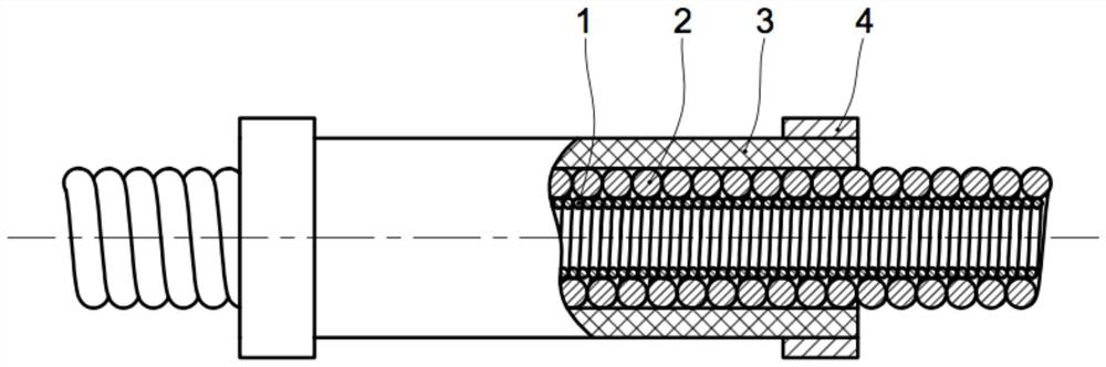
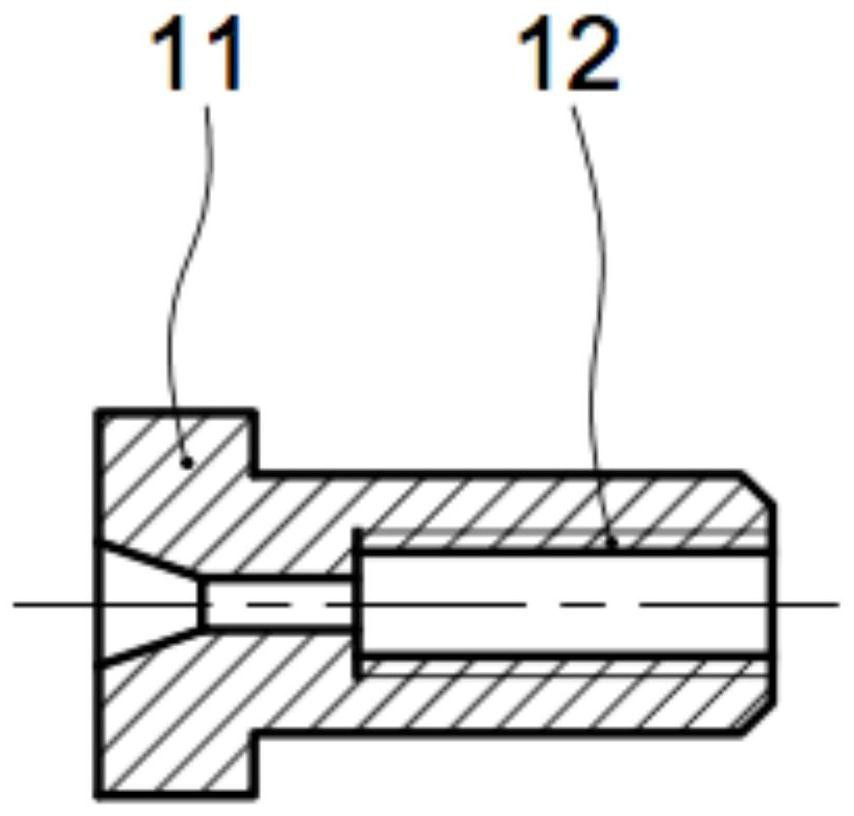
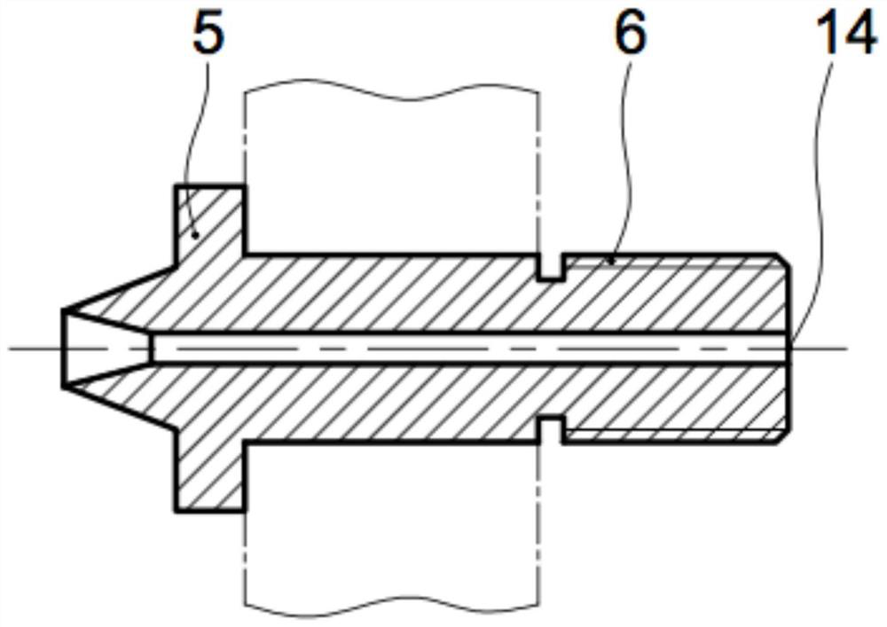
[0040] figure 1 A schematic diagram of the reinforcement device of the wire conveying channel of the special MIG / MAG welding equipment of the present invention is shown. The welding wire conveying channel reinforcement device includes a reinforcement inner pipe 1, a reinforcement outer pipe 2, an insulating jacket 3, a throat hoop 4, a wire feed joint 5, an anti-displacement joint 11 and an outer pipe seat. The reinforced inner pipe 1, the reinforced outer pipe 2, and the insulating jacket 3 are nested in sequence from the inside to the outside and then fastened by the throat hoop 4. The outer tube seat includes a wire inlet end outer tube seat 7 and a wire outlet end outer tube seat 13 .

[0041] The reinforced inner tube 1 does not need to be customized, and the wire spring hose is modified (only the required length is intercepted). The outer diameter of the wire spring hose should be determined according to the inner diameter of the designed reinforced outer tube 2.

[00...


PUM

PropertyMeasurementUnit
angleaaaaaaaaaa
diameteraaaaaaaaaa
diameteraaaaaaaaaa

Abstract

The welding wire conveying channel reinforcing device special for the gas metal arc welding equipment comprises a reinforcing inner pipe (1), a reinforcing outer pipe (2) and a reinforcing inner pipe (3), the reinforcing outer tube (2) adopts a densely-wound bourdon tube, the wire diameter of the densely-wound bourdon tube is 2-3 times that of the reinforcing inner tube (1), every two circles of the densely-wound bourdon tube are spot-welded one by one, and welding spots are in a spiral line shape in the length direction of the densely-wound bourdon tube; an insulating jacket (3); the anti-displacement joint is used for fixing and reinforcing the inner pipe (1) from the wire feeding end so as to prevent the inner pipe (1) from axially displacing under the action of wire feeding thrust; the wire feeding connector is installed behind a wire feeding wheel of the wire feeding mechanism and connected with the wire feeding end outer pipe seat, the inner pipe anti-displacement connector and the reinforcing inner pipe (1) are installed at the wire feeding end of the wire feeding end outer pipe seat firstly, then the wire feeding end of the wire feeding end outer pipe seat is connected with one end of the reinforcing outer pipe (2), and the other end of the reinforcing outer pipe (2) is connected with the wire discharging end outer pipe seat (13). The device allows the welding wire conveying channel to deform in any space in the working state.

Description

technical field [0001] The invention relates to a welding wire conveying channel reinforcement technology, in particular to a welding wire reinforcement technology of a welding wire conveying channel of a gas shielded welding equipment under the application condition of a special machine (non-universal equipment), and belongs to the field of welding technology. Background technique [0002] The MIG / MAG welding method is the most widely used welding method in the field of arc welding. There are two main types of equipment corresponding to the MIG welding method: one is general MIG welding equipment, and the other is special (non-universal) MIG welding equipment. Both general-purpose and special-purpose equipment need to send the welding wire from the wire reel (or barreled welding wire) to the end of the contact tip of the welding gun through the friction force generated by the wire feeding mechanism, from the wire feeding drive wheel of the wire feeding mechanism to the cont...

Claims


Application Information

Patent Timeline
Patent Type & Authority Applications(China)
IPC IPC(8): B23K9/133B23K9/173
CPCB23K9/133B23K9/173
Inventor 张富巨张瑞李小康
Owner 武汉纳瑞格智能设备有限公司
Why Eureka
Try Eureka