Large-span cable-stayed bridge girder erection method

A cable-stayed bridge and long-span technology, which is applied in the direction of cable-stayed bridges, bridge construction, bridges, etc., can solve the problem that the main girder section does not have direct vertical lifting installation conditions, the alignment of the main girder is difficult to ensure, and the construction of the main girder is difficult, etc. problem, to achieve the effect that the alignment of the main girder is easy to ensure, the quality of bridge construction is improved, and the difficulty of installation and operation is low

Pending Publication Date: 2022-03-25
ROAD & BRIDGE INT +1
View PDF9 Cites 1 Cited by
  • Summary
  • Abstract
  • Description
  • Claims
  • Application Information

AI Technical Summary

Problems solved by technology

[0002] During the construction of the bridge, due to the constraints of terrain, navigation, or existing property rights under the bridge, the main girder section does not have the conditions for direct vertical lifting and installation, resulting in difficulties in the construction of the main girder.
At present, the cantilever assembly technology of bridge deck crane is usually used, but this construction method requires the steel structure of the main girder to be an orthotropic steel girder. The components are transported to the bridge deck crane and assembled one by one. This construction method is relatively slow in assembly speed, and the alignment of the main girder is not easy to ensure

Method used


Image

  • Large-span cable-stayed bridge girder erection method
  • Large-span cable-stayed bridge girder erection method
  • Large-span cable-stayed bridge girder erection method

Examples


Embodiment Construction

[0059] Embodiments of the present invention are described in detail below, examples of which are shown in the drawings, wherein the same or similar reference numerals designate the same or similar elements or elements having the same or similar functions throughout. The embodiments described below by referring to the figures are exemplary only for explaining the present invention and should not be construed as limiting the present invention.

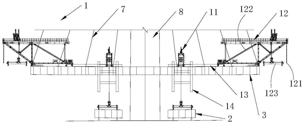
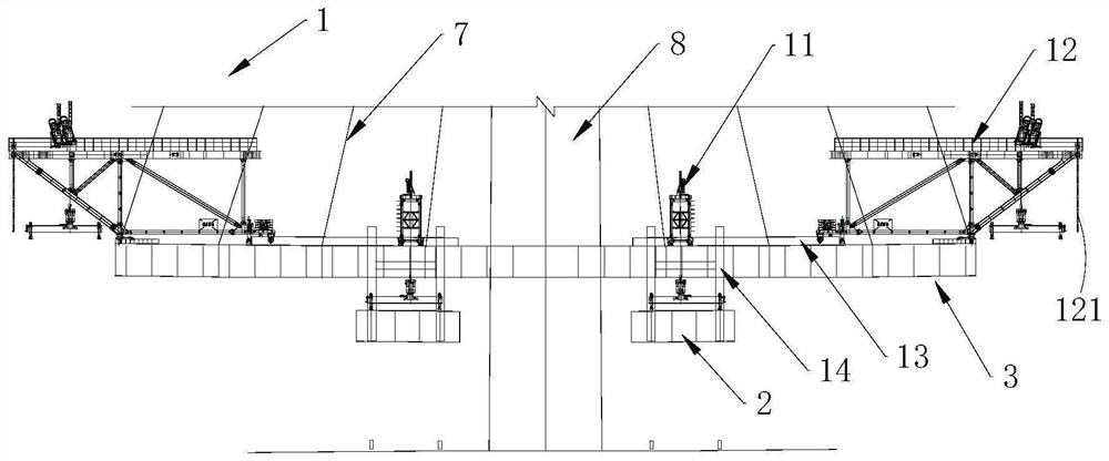
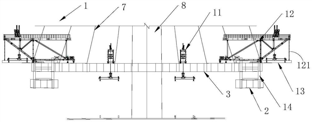
[0060] Such as Figures 1 to 7 As shown, the present invention provides a long-span cable-stayed bridge main girder erection construction system 1, comprising a first hoisting device, a slideway (not shown in the figure), a linear transfer device and a second hoisting device, the first hoisting device A lifting device is used to lift the beam section 2 to be installed to the linear transfer device, and the slideway is used to provide a moving guide for the linear transfer device, and the linear transfer device is used to lift the beam se...


PUM


Abstract

The invention provides a girder erection method for a large-span cable-stayed bridge. The girder erection method for the large-span cable-stayed bridge is characterized by comprising the following steps that a main tower, an auxiliary pier and a transition pier are erected, and a preset height is reserved between the top of the auxiliary pier and a girder; building a tower area beam section at the main tower; a main beam erection construction system is installed on the tower area beam section; after being integrally lifted, the single to-be-mounted beam section is horizontally transferred to the front end of the mounted beam section to be mounted; repeating the previous step until the main beam is spliced to the auxiliary pier; heightening construction is conducted on the auxiliary piers so that the auxiliary piers can be connected with the main beam; and repeatedly executing the step of integrally lifting the single to-be-mounted beam section and then horizontally transferring the single to-be-mounted beam section to the front end of the mounted beam section for mounting until the main span is closed. According to the construction method, the overall installation and assembly precision of the girder sections is high, the line shape of the girder is easy to guarantee, the bridge construction quality is high, and the construction speed is higher.

Description

technical field [0001] The invention relates to the technical field of bridge construction, in particular to a method for erecting a main girder of a long-span cable-stayed bridge. Background technique [0002] During the bridge construction process, the main girder section does not have the conditions for direct vertical lifting and installation due to the terrain, navigation, or existing property rights under the bridge, which makes the construction of the main girder difficult. At present, the cantilever assembly technology of bridge deck crane is usually used, but this construction method requires the steel structure of the main girder to be an orthotropic steel girder. The components are transported to the bridge deck crane and assembled one by one. This construction method is relatively slow in assembly speed, and the alignment of the main girder is not easy to guarantee. Contents of the invention [0003] The purpose of the present invention is to provide a method ...

Claims


Application Information

Patent Timeline
Patent Type & Authority Applications(China)
IPC IPC(8): E01D21/00E01D21/10E01D11/04
CPCE01D21/00E01D21/10E01D11/04
Inventor 张皎吴健史双涛温东昌马水英肖英陈小龙王海伟张敬弦
Owner ROAD & BRIDGE INT
Why Eureka
Try Eureka