

Frame type drilling device and construction method
The technology of a drilling device and construction method, which is applied in the direction of drilling equipment and methods, supporting devices, drilling equipment, etc., can solve the problems of cumbersome continuous drilling procedures, achieve various rock breaking methods, reduce the number of times of hole washing, and improve efficiency Effect
- Summary
- Abstract
- Description
- Claims
- Application Information
AI Technical Summary
Problems solved by technology
Method used
Image

Examples
Embodiment 2
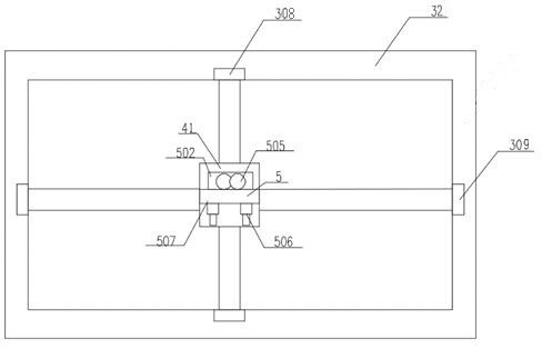
[0065] Example 2, such as image 3 As shown, the difference between it and Embodiment 1 is that at least two drilling devices are provided on the base A41, and the drill bit 505 of the drilling device can be flushed forward to drill holes to improve drilling efficiency; the drill bit can also be retracted. 505, and allow one of the drill bits 505 to be in the borehole as a guide for connecting hole drilling.
Embodiment 3
[0066] Example 3, such as Figure 4~Figure 12 As shown, the difference between it and Embodiment 1 is that, preferably, the support frame 3 is a circular frame 31, and the moving mechanism includes a turntable A61 that is connected to the circular frame 31 for movement and rotation, and a drive turntable A61 to move and rotate. The transfer mechanism A; the drilling equipment is slidably connected to the turntable A61. Wherein, the turntable A61 is located in the circular frame 31, and the transfer mechanism A drives the turntable A61 to move and rotate within the plane defined by the circular frame 31, thereby driving the drilling equipment to move and rotate.
[0067] Preferably, as Figure 4~Figure 9 As shown, the transfer mechanism A includes at least two transfer telescopic drive parts A305 connected to the circular frame 31, and the working end of the transfer telescopic drive part A305 is provided with a rotatable gear and a drive for driving the gear to rotate. Parts...
Embodiment 4
[0078] Example 4, such as Figure 13~Figure 15 As shown, the difference between it and Embodiment 1 is that the support frame 3 is connected to the trolley 1 through at least two swing arms 7; the support frame 3 is an arc frame 33, and the moving mechanism includes an arc frame 33 moves and rotates the connected turntable B62 and the transfer mechanism B that drives the turntable B62 to move and rotate; the drilling equipment is slidably connected to the turntable B62; the transfer mechanism B includes at least two moving parts connected to the arc frame 33 Turn the telescopic driver B310, and shift the working end of the telescopic driver B310 to be provided with a rotatable gear 3101 and a driving member that the drive gear 3101 rotates; the turntable B62 is provided with a ring gear meshed with the gear 3101; The working end of the telescopic driver B310 is provided with a limit baffle B3102 that limits the turntable B62 to prevent the axial relative displacement between t...
PUM
 Abstract
Description
Claims
Application Information