Electric barring gear

An electric cranking and cranking technology, which is applied to the components, engine components, machines/engines, etc. of the pumping device for elastic fluid, can solve the problems of increased equipment investment, inability to output in two directions, inconvenience, etc., and can reduce equipment Small footprint, saving time, simple and compact structure

Pending Publication Date: 2022-03-25
沈阳北碳密封有限公司
View PDF0 Cites 0 Cited by
  • Summary
  • Abstract
  • Description
  • Claims
  • Application Information

AI Technical Summary

Problems solved by technology

[0004] 1. The start and stop are mostly manually operated on site. With the development of automation technology, if the mechanical equipment to be turned needs to be remotely controlled, the turning device needs to be manually started and stopped, which is very inconvenient.
[0005] 2. There is no anti-reversal function of the host (device being disk)
At this time, if the cranking device has not been disconnected from the main engine, after the rotor reverses, the output speed of the cranking device with a speed of zero is "higher than" the reverse rotation speed of the rotor, which meets the meshing condition, and the cranking device will not be connected with the rotor in time. The main engine is disconnected, resulting in a runaway failure, which completely damages the cranking device
[0006] 3. Most of them can only output in one direction, not in two directions
For the equipment with positive and negative output during the test run, two turning devices with forward output and reverse output need to be equipped, and both turning devices need to have anti-reverse function, which not only increases equipment investment, but also increases equipment occupation. Floor space and time required to replace equipment

Method used


Image

  • Electric barring gear

Examples


Embodiment Construction

[0025] The present invention will be further described below in conjunction with drawings and embodiments.

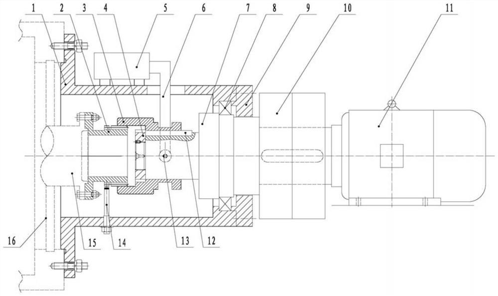
[0026] combine figure 1 , the embodiment of the present invention includes a casing 1 installed on the host machine 16 through a flange connection, a bidirectional gear motor 11 installed on the ground (the gear motor can be a single low-speed motor or a combination of a motor and a gear reducer), a transmission Mechanism, positive and negative rotational speed monitoring protection device and safety clutch 10.

[0027] The transmission mechanism includes a turning gear 2, a transmission sleeve 3 and a driving sleeve toggle device; the front end of the turning gear (close to the host end) is connected to the main engine main shaft 15 through a flange, and the outer circle of the turning gear is processed with a transmission outer ring. Gears and gears for speed reversal detection; the front section of the transmission sleeve has internal teeth that can mesh with the tr...


PUM


Abstract

An electric barring gear comprises a machine shell, a gear motor capable of rotating in two directions, a transmission mechanism and a positive and negative rotating speed monitoring protector. The transmission mechanism comprises a turning gear connected with a main shaft of the main machine, a transmission sleeve of which the front section can be meshed with the turning gear and the rear section is in sliding connection with the main shaft through a transmission key, and a transmission sleeve shifting device consisting of an electric push rod and a shifting fork connected with the electric push rod and of which the lower end is arranged in an excircle groove of the transmission sleeve; a sensor probe of the positive and negative rotation speed monitoring protection instrument is mounted on the inner wall of the shell corresponding to a rotation speed reverse rotation detection gear of the turning gear and is used for measuring the rotation speed and the rotation direction of the turning gear; a safety clutch connected with the gear motor is installed at the tail of the main shaft. The turning gear is automatically controlled to start and stop, and manual operation is not needed; and bidirectional output can be realized by matching with a motor capable of rotating in two directions, and the function of preventing the host from rotating reversely in two directions is realized.

Description

technical field [0001] The invention relates to the technical field of barring, in particular to an electric barring device for large equipment such as a turbine, a large motor, a large fan, and a compressor. Background technique [0002] As we all know, the large rotors of turbines, large motors, large fans, compressors and other machinery need to be dribbled with electric barring devices before starting or after stopping, so as to prevent equipment accidents and improve the service life of the rotors. [0003] The existing electric barring device has the following technical problems: [0004] 1. The start and stop are mostly manually operated on site. With the development of automation technology, if the mechanical equipment to be turned needs to be remotely controlled, the turning device still needs to be manually started and stopped, which is very inconvenient. [0005] 2. There is no function of anti-host (device under disk) reversal. Once the reverse rotation fault o...

Claims


Application Information

Patent Timeline
IPC IPC(8): F01D25/36F04D29/00F04C29/00
CPCF01D25/36F04D29/002F04C29/00
Inventor 崔正军刘帅高升召
Owner 沈阳北碳密封有限公司
Why Eureka
Try Eureka