Method for evaluating array direction finding precision under near-end multipath condition

A near-end and array technology, applied in the field of array direction finding, can solve problems such as time-consuming, complex modeling, and inability to intuitively analyze the influence of near-end multipath

Active Publication Date: 2022-03-25
SOUTHWEST CHINA RES INST OF ELECTRONICS EQUIP
View PDF3 Cites 0 Cited by
  • Summary
  • Abstract
  • Description
  • Claims
  • Application Information

AI Technical Summary

Problems solved by technology

That is, first model the antenna pattern and simulate the antenna pattern, then model and simulate the antenna and reflective objects to obtain the antenna pattern in the case of near-end multipath, and then obtain the amplitude difference between the antenna elements caused by the near-end multipath effect, Finally, the direction

Method used


Image

  • Method for evaluating array direction finding precision under near-end multipath condition
  • Method for evaluating array direction finding precision under near-end multipath condition

Examples


Embodiment 1

[0049] Embodiment 1: A method for evaluating array direction finding accuracy under near-end multipath conditions, including:

[0050] Step S1, constructing the array flow pattern according to the spatial arrangement position relationship of the array elements;

[0051] Step S2, setting the incident wave direction of a single signal;

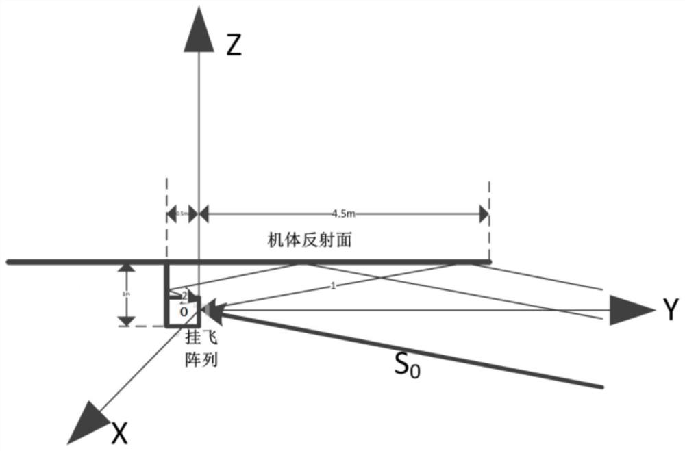
[0052] Step S3, determining the reflection coefficient, the array near-end multipath signal path, the number of multipath signals and the multipath signal angle according to the relative positional relationship between the antenna array and the near-end strong scatterer;

[0053] Step S4, describing the complex vector form of the multipath signal;

[0054] Step S5, synthesizing the complex vector form of the multipath signal and the incident signal vector into a synthesized signal vector form on the complex plane;

[0055] In step S6, the synthetic signal vector form is substituted into the array direction-finding algorithm, and the array dire...

Embodiment 2

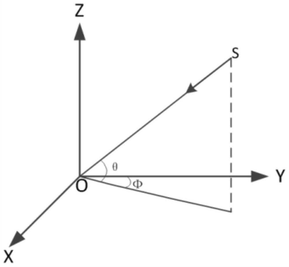
[0056]Embodiment 2: On the basis of Embodiment 1, the construction of the array flow pattern according to the spatial arrangement position relationship of the array elements includes the following two construction methods: setting a certain frequency f 0 Signal, in the darkroom environment, discretely set the incident wave space angle, and obtain the amplitude and phase parameters of each element of the receiving array; or set a certain frequency f 0 Signal, the incident wave space angle is set discretely, and the amplitude and phase parameters of each array element of the receiving array are calculated according to the array element arrangement relationship; among them, the incident space angle (Ф i , θ j ), i=1, 2,..., N; j=1, 2,..., N, Ф i is the azimuth angle of the incident signal, θ j is the pitch angle of the incident signal, i and j are the discrete points of the incident signal angle respectively, N×N angles are arranged according to the two-dimensional array, and N...

Embodiment 3

[0057] Embodiment 3: On the basis of Embodiment 1, the setting of the incident wave direction (Ф, θ) of a single signal includes sub-steps: setting a vector representation of a far-end incident signal as: u 0 (t) is the received signal gain of the array element, is the initial phase, ω 0 =2πf 0 is the frequency of the incident signal.


PUM


Abstract

The invention discloses a method for evaluating array direction finding precision under a near-end multipath condition, and belongs to the field of array direction finding, and the method comprises the steps: constructing an array flow pattern according to an array element space arrangement position relation; setting a single signal incident wave direction; determining a reflection coefficient, an array near-end multi-path signal path, a multi-path signal quantity and a multi-path signal angle according to a relative position relationship between the antenna array and a near-end strong scatterer; describing a complex vector form of the multipath signal; synthesizing the complex vector form of the multipath signal and the incident signal vector into a synthesized signal vector form on a complex plane; and the vector form of the synthesized signal is substituted into an array direction finding algorithm, an array direction finding angle under a near-end multipath condition is simulated and calculated, the calculated angle is compared with an incident wave theoretical angle, and a direction finding error caused by a near-end multipath effect is rapidly evaluated. The method is suitable for the evaluation of the array direction finding precision under the condition that a near-end strong scatterer generates a multipath signal and the evaluation of the influence of a far-end multipath effect on the array direction finding precision, and has universality.

Description

technical field [0001] The invention relates to the field of array direction finding in signal processing, and more specifically, to an evaluation method for array direction finding accuracy under near-end multipath conditions. Background technique [0002] The existing method for evaluating the direction-finding accuracy affected by multipath effects is the method for evaluating the direction-finding accuracy affected by far-end multipath effects. This type of evaluation method mainly adopts the principle of mirror reflection to establish a multipath transmission model, and analyzes the amplitude difference and phase difference change of the received signal between the antenna array elements when the remote multipath signal enters the antenna. Cross-beam direction finding, interferometer direction finding, circular array correlation method direction finding, etc. derive the direction finding error formula, bring the amplitude difference and phase difference error under the ...

Claims


Application Information

Patent Timeline
IPC IPC(8): G06F30/20G06F17/16
CPCG06F30/20G06F17/16
Inventor 梁永生左乐何晓英王茂泽聂剑坤朱全江谢成城饶亮刘长江
Owner SOUTHWEST CHINA RES INST OF ELECTRONICS EQUIP
Why Eureka
Try Eureka