Airtight metal packaging structure and manufacturing method

A technology of metal packaging and manufacturing methods, which is applied in the direction of metal processing equipment, coupling devices, electrical components, etc., can solve the problems of poor airtightness of aluminum alloy box welding, and achieve airtightness, high strength, and airtightness good effect

Pending Publication Date: 2022-03-25
THE 13TH RES INST OF CHINA ELECTRONICS TECH GRP CORP
0 Cites 1 Cited by

AI-Extracted Technical Summary

Problems solved by technology

[0004] The embodiment of the present invention provides an airtight metal packaging structure...

Method used

The airtight metal encapsulation structure that present embodiment provides, compared with prior art, in aluminum alloy box body 1 local welding silicon-aluminum composite material, multi-core connector is welded to silicon-aluminum material position, because silicon-aluminum The thermal expansion coefficient of the composite material is 7.2, which is relatively close to Kovar alloy, which can ensure good airtightness after welding and environmental tests, thereby solving the airtightness proble...

Abstract

The invention provides an airtight metal packaging structure and a manufacturing method, and belongs to the technical field of metal packaging, the airtight metal packaging structure comprises an aluminum alloy box body, a silicon-aluminum sealing element and a multi-pin-core connector, and the side wall of the aluminum alloy box body is provided with a first mounting hole; the silicon-aluminum sealing element is arranged in the first mounting hole, and a second mounting hole is formed in the silicon-aluminum sealing element; and the multi-pin core connector is arranged in the second mounting hole. According to the airtight metal packaging structure provided by the invention, the silicon-aluminum composite material is welded on the part, where the multi-pin core connector is welded, of the aluminum alloy box body in a diffusion welding manner, and the multi-pin core connector is welded to the position of the silicon-aluminum composite material, so that the problem that the thermal expansion coefficients of aluminum alloy and the multi-pin core connector are not matched is solved; meanwhile, as the main body material is the aluminum alloy, the problem of low strength of the silicon-aluminum material is solved, the air tightness of the metal packaging is realized, the strength of the metal packaging is ensured, and the metal packaging structure has a huge application prospect in the metal packaging.

Application Domain

Contact member cases/bases manufactureSoldering apparatus +5

Technology Topic

Aluminum compositesAluminium alloy +5

Image

  • Airtight metal packaging structure and manufacturing method
  • Airtight metal packaging structure and manufacturing method
  • Airtight metal packaging structure and manufacturing method

Examples

  • Experimental program(1)

Example Embodiment

[0030] In order to make the technical problems, technical solutions and beneficial effects to be solved by the present invention clearer, the present invention will be further described in detail below with reference to the accompanying drawings and embodiments. It should be understood that the specific embodiments described herein are only used to explain the present invention, but not to limit the present invention.
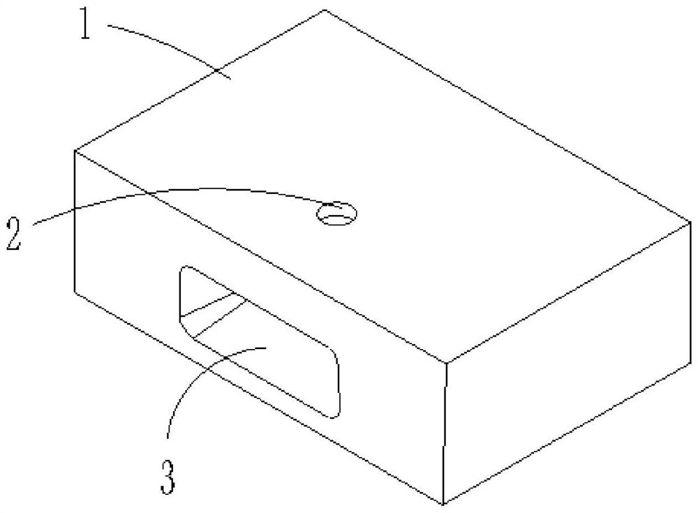
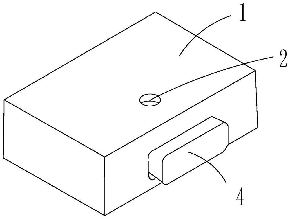
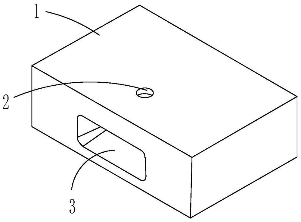
[0031] Please also refer to Figure 1 to Figure 7 , the airtight metal package structure provided by the present invention will now be described. The airtight metal packaging structure includes an aluminum alloy box 1, a silicon-aluminum seal 4 and a multi-pin connector 6. The side wall of the aluminum alloy box 1 is provided with a first mounting hole 3; the silicon-aluminum seal 4 It is arranged in the first installation hole 3 , and the silicon-aluminum sealing member 4 is provided with a second installation hole 5 ; the multi-pin connector 6 is arranged in the second installation hole 5 .
[0032] Compared with the prior art, in the airtight metal package structure provided in this embodiment, the silicon-aluminum composite material is partially welded to the aluminum alloy box 1, and the multi-core connector is welded to the position of the silicon-aluminum material. The thermal expansion coefficient is 7.2, which is close to Kovar alloy, which can ensure good air tightness after welding and environmental testing, thus solving the air tightness problem of metal-encapsulated multi-pin connector 6 after welding, and at the same time ensuring metal The package has high strength.
[0033] As an embodiment of the silicon-aluminum sealing member 4 in this embodiment, see Figure 1 to Figure 3 , the silicon-aluminum sealing member 4 is a conical structure, and the silicon-aluminum sealing member 4 is an interference fit with the first installation hole 3 . The silicon-aluminum sealing member 4 with the conical structure has a positioning function, which facilitates the welding and fixing of the silicon-aluminum sealing member 4 .
[0034] A variant embodiment of the above-mentioned characteristic silicon-aluminum seal 4 is, see Figure 4 , the second mounting hole 5 is provided with a stepped hole, and the multi-pin connector 6 is arranged in the stepped hole. The provided stepped holes facilitate the plugging of electrical components plugged with the multi-pin connector 6 .
[0035] Based on the above-mentioned silicon aluminum seal 4, see Figure 1 to Figure 3 As another variant embodiment of the aluminum alloy box body 1 , the bottom plate of the aluminum alloy box body 1 is provided with an exhaust hole 2 that is vertically communicated with the first installation hole 3 . The set exhaust hole 2 is used for exhaust gas during welding, and the welding quality is improved.
[0036] Based on the above-mentioned silicon aluminum seal 4, see Figure 4 to Figure 6 , as another variant embodiment of the aluminum alloy box body 1 , the opening of the aluminum alloy box body 1 is provided with a support step 7 , and the support step 7 is provided with a box cover 8 . On the one hand, the box cover 8 is positioned, and on the other hand, the box cover 8 is flush with the upper surface of the aluminum alloy box body 1 .
[0037] On the basis of the silicon-aluminum sealing member 4 and the aluminum alloy box body 1 , a nickel-gold layer is plated in the second mounting hole 5 . In order to protect the multi-pin core connector 6, it is also convenient for welding.
[0038] Based on the same inventive concept, an embodiment of the present application further provides a method for fabricating the airtight metal package structure, the method comprising:
[0039] In step 1, a first installation hole 3 is arranged on the side wall of the aluminum alloy box body 1, and an exhaust hole 2 communicated with the installation hole is arranged on the aluminum alloy box body 1; see figure 1;
[0040] Step 2: Weld the silicon aluminum seal 4 in the first mounting hole 3, see figure 2 and image 3;
[0041] Step 3: Process the second mounting hole 5 on the silicon-aluminum seal 4, see Figure 4 and Figure 5;
[0042] Step 4, electroplating nickel-gold in the second mounting hole 5;
[0043] Step 5: Solder the multi-pin connector 6 in the second mounting hole 5, see Image 6.
[0044] As a possible implementation manner of step 2, the silicon-aluminum sealing member 4 is welded in the first mounting hole 3 by diffusion welding, and external pressure is applied during welding.
[0045] Compared with other welding methods, diffusion welding has the following advantages:
[0046] 1) During diffusion welding, since the matrix is ​​not overheated and does not melt, almost all metals or non-metals can be welded without reducing the performance of the material to be welded, especially suitable for fusion welding and other materials that are difficult to weld, such as active metals, Heat-resistant alloys, ceramics and composites, etc. Diffusion welding is a suitable welding method for the same materials with poor plasticity or high melting point, as well as dissimilar materials that are immiscible or produce brittle intermetallic compounds during fusion welding.
[0047] 2) The quality of the diffusion welded joint is good, and its microstructure and properties are close to or the same as those of the base metal. There is no fusion welding defect in the weld, and there is no overheated structure and heat affected zone. Welding parameters are easy and precise to control, and joint quality and performance are stable during mass production.
[0048] 3) The weldment has high precision and small deformation. Due to the small pressure applied during welding, the workpiece is mostly heated as a whole and cooled with the furnace, so the overall plastic deformation of the weldment is very small, and the workpiece after welding is generally no longer machined.
[0049] 4) Large-section workpieces can be welded because the pressure required for welding is not large, so the tonnage of the equipment required for large-section welding is not high, which is easy to implement.
[0050] 5) Workpieces with complex structures, inaccessible joints and large thickness differences can be welded, and many joints in the assembly can be welded at the same time.
[0051]The disadvantages of diffusion welding are as follows:
[0052] 1) The preparation and assembly quality requirements of the weldment surface are high, especially for the joint surface.
[0053] 2) The welding thermal cycle time is long and the productivity is low. Each welding is as fast as a few minutes and as slow as dozens of hours. For some metals, it will cause grain growth.
[0054] 3) The one-time investment of equipment is large, and the size of the welding workpiece is limited by the equipment, so continuous mass production cannot be carried out.
[0055] Diffusion welding is especially suitable for small parts that require vacuum sealing, the strength of the joint and the base metal, and no deformation. It is the only way to make vacuum-tight, heat-resistant, vibration-resistant and non-deformation joints, so it is widely used in industrial production. Diffusion welding is used in the welding of metals and non-metals in electric vacuum equipment, and the welding of cemented carbide, ceramics, high-speed steel and carbon steel in cutting tools.
[0056] As a possible implementation of step 6, see Image 6 , the multi-pin core connector 6 is welded in the second mounting hole 5 by brazing.
[0057] Brazing refers to a welding method in which the filler metal and the weldment below the melting point of the weldment are heated to the melting temperature of the filler metal at the same time, and then the liquid filler metal is used to fill the gap of the solid workpiece to connect the metals. During brazing, the oxide film and oil stains on the contact surface of the base metal should be removed first, so that the capillary can play a role after the brazing filler metal is melted and increase the wettability and capillary fluidity of the brazing filler metal. According to the different melting points of the solder, brazing is divided into brazing and soldering.
[0058] The brazing deformation is small, the joints are smooth and beautiful, and it is suitable for welding precision, complex and components composed of different materials, such as honeycomb structure plates, turbine blades, carbide cutting tools and printed circuit boards. Before brazing, the workpiece must be carefully processed and strictly cleaned to remove oil stains and excessively thick oxide film to ensure the interface assembly gap. The gap is generally required to be between 0.01 and 0.1 mm.
[0059] Compared with fusion welding, the base metal is not melted during brazing, only the brazing material is melted; compared with pressure welding, no pressure is applied to the weldment during brazing. The weld formed by brazing is called brazing. The filler metal used for brazing is called brazing filler metal.
[0060] Brazing process: The workpieces that have been cleaned on the surface are assembled together in a lap joint pattern, and the solder is placed near or between the joint gaps. When the workpiece and the solder are heated to a temperature slightly higher than the melting point of the solder, the solder melts (the workpiece is not melted), and is sucked in by capillary action and fills the gap between the solid workpieces. The liquid solder and the workpiece metal diffuse and dissolve with each other. A brazed joint is formed after condensation.
[0061] Vacuum diffusion welding and vacuum brazing are two completely different welding methods. Vacuum diffusion is a kind of vacuum that is carried out in a vacuum, and the weldments are closely attached, and maintained for a period of time under the appropriate temperature and pressure (workpiece bonding pressure), so that the interatomic diffusion occurs between the contact surfaces, thereby The welding method used to form the joint. Vacuum diffusion can be carried out between metal and metal, or between metal and ceramic. Vacuum brazing: It uses a metal material with a liquidus temperature lower than the solidus temperature of the base metal as the brazing material, heats the parts and the brazing material until the brazing material melts, and uses the liquid brazing material to wet the base metal, fill the joint gap and It dissolves and diffuses with the base metal, and then the liquid solder crystallizes and solidifies, so as to realize the connection of the parts (the welded part does not melt, only the solder melts). Both can be welded in vacuum, but also in protective gas.
[0062] In this embodiment, see Figure 7 , the lid 8 of the aluminum alloy box body 1 is encapsulated by laser.
[0063] The present invention provides an air-tight metal packaging structure. The silicon-aluminum composite material is welded to the part of the aluminum alloy box body 1 where the multi-pin core connector 6 is welded by means of diffusion welding, and the multi-pin core connector 6 is welded to the silicon-aluminum alloy. The position of the material solves the problem that the thermal expansion coefficient of the aluminum alloy and the multi-pin connector 6 does not match. At the same time, because the main material is aluminum alloy, it solves the problem of low strength of the silicon-aluminum material. This structure not only realizes the airtightness of the metal package It also ensures the strength of metal packaging, and has huge application prospects in metal packaging.
[0064] The above descriptions are only preferred embodiments of the present invention and are not intended to limit the present invention. Any modifications, equivalent replacements and improvements made within the spirit and principles of the present invention shall be included in the protection of the present invention. within the range.

PUM

no PUM

Description & Claims & Application Information

We can also present the details of the Description, Claims and Application information to help users get a comprehensive understanding of the technical details of the patent, such as background art, summary of invention, brief description of drawings, description of embodiments, and other original content. On the other hand, users can also determine the specific scope of protection of the technology through the list of claims; as well as understand the changes in the life cycle of the technology with the presentation of the patent timeline. Login to view more.

Similar technology patents

Preparation method of a special composite structure riser for low pressure casting

InactiveCN101413605BGood thermal shock resistanceGood air tightness
Owner:SINOSTEEL LUOYANG INST OF REFRACTORIES RES

Novel artificial alveolar model

Owner:SUZHOU SINGMED MEDICAL DEVICE SCI & TECH LTD

Classification and recommendation of technical efficacy words

  • Good air tightness
  • Solve the problem of airtightness

Smelting and updraft continuous casting process of Cu-Cr-Zr alloy

ActiveCN101618445AGood air tightness
Owner:苏州中色华人铜业有限公司

Optical fiber airtightly leading out method for GIS cavity

ActiveCN101710201ASolve the problem of airtightnessReduce fusion joints
Owner:NARI TECH CO LTD

Double-waveguide/multi-waveguide channel structure working in W wave band and TR module

ActiveCN113437464Aavoid mutual interferenceSolve the problem of airtightness
Owner:CHENGDU THUNDER MICROCRYSTALLINE TECH CO LTD
Why Eureka
Try Eureka