Valve assembly, heat exchange assembly, cabinet, cabinet cluster temperature control system and method and air conditioner room

A technology of valve components and cabinets, applied in the modification of standard racks/cabinets, valve devices, sliding valves, etc., can solve problems such as uneven air supply volume, downtime accidents, and ambient temperature exceeding the operating temperature range of equipment in the cabinet , to achieve the effect of increasing the cooling capacity

Active Publication Date: 2022-03-25
GREE ELECTRIC APPLIANCES INC
View PDF26 Cites 2 Cited by
  • Summary
  • Abstract
  • Description
  • Claims
  • Application Information

AI Technical Summary

Problems solved by technology

[0004] The purpose of the present invention is to solve the uneven air supply to each cabinet in the current multi-cabinet machine room, which can easily cause the ambie...

Method used


Image

  • Valve assembly, heat exchange assembly, cabinet, cabinet cluster temperature control system and method and air conditioner room
  • Valve assembly, heat exchange assembly, cabinet, cabinet cluster temperature control system and method and air conditioner room
  • Valve assembly, heat exchange assembly, cabinet, cabinet cluster temperature control system and method and air conditioner room

Examples


Embodiment 1

[0052] [Embodiment 1 related valve assembly]

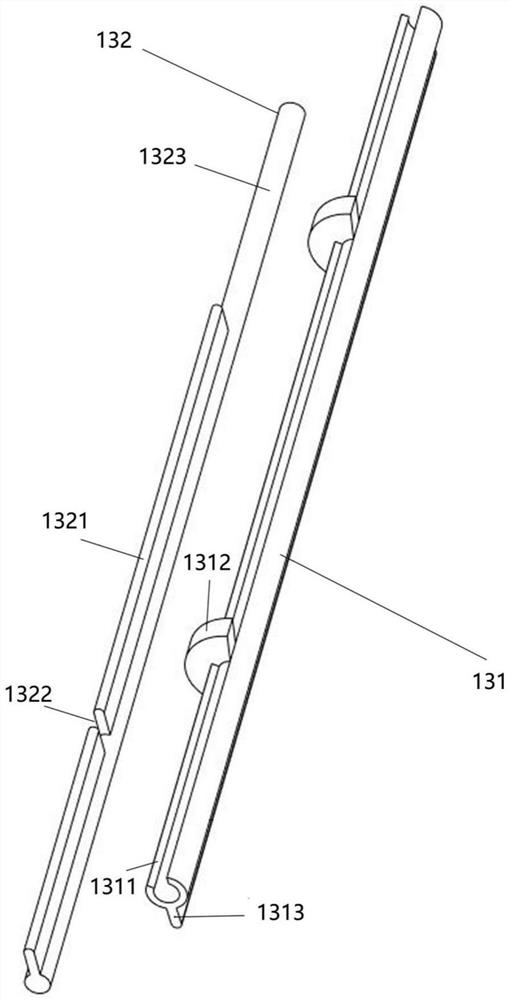
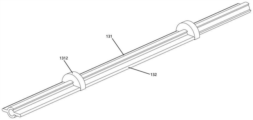
[0053] Such as Picture 1-1 , 1-2 , 2-1 to 2-3, a valve assembly provided in this embodiment is suitable for being arranged in a manifold, the main inventive concepts and corresponding structures are as follows:

[0054] Including stator valve plate 131, rotor valve plate 1323 and driving device;

[0055] The length direction of the stator valve plate 131 is parallel to the length direction of the rotor valve plate 132, and the first end of the width direction of the stator valve plate 131 forms a hinged groove (referred to as a shaft sleeve 1311 in the following specific embodiments). The first end in the width direction of the rotor valve plate 132 forms a hinged shaft (referred to as the rotating shaft 1323 in the following specific embodiments), and the rotating shaft 1323 is embedded in the shaft sleeve 1311 and can rotate at a certain angle relative to the shaft sleeve 1311; The second end in the width direction of the sta...

Embodiment 2

[0066] [Embodiment 2 about the heat exchange assembly]

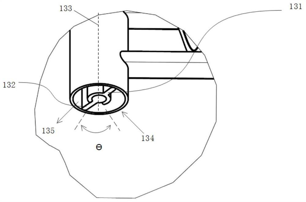
[0067] Such as Figure 2-1~2-3 As shown, a heat exchange assembly embodiment of the heat exchange assembly of the present invention includes a microchannel heat exchanger 120 and a valve assembly 130 as described above in any embodiment of the valve assembly of the present invention, and the microchannel heat exchanger (120) includes a microchannel Heat exchange tubes and manifolds, the valve assembly 130 is arranged in the manifold of the microchannel heat exchanger 120, the liquid inlet channel 134 of the valve assembly 130, the heat exchange tube of the microchannel heat exchanger 120 and the liquid outlet channel of the valve assembly 130 135 and the three are connected to form a circulation flow channel. In this embodiment, the valve assembly 130 and the microchannel heat exchanger 120 are combined into a heat exchange assembly, which can realize the regulation of liquid flow in the microchannel heat exchanger 120,...

Embodiment 3

[0068] [Cabinet related to Embodiment 3]

[0069] Such as image 3 Shown is an embodiment of the cabinet of the present invention, which is provided with the heat exchange assembly of any one of the above embodiments of the present invention.

[0070] Specifically, the cabinet includes a front door panel 110 and a cabinet body 20. The heat exchange components are laid on the inner side wall of the front door panel 110, and the length and width of the laying are equivalent to the size of the front door panel 110, so as to fully cover the equipment space in the cabinet. . The cabinet body 20 includes an outer frame 400 , a rear door panel 300 and a plug box 200 disposed on the outer frame 400 , and the front door panel 110 and the rear door panel 300 are hollow structures. The cold air enters the cabinet from the front door panel 110, and then exchanges heat with the micro-channel heat exchanger 120 to be further cooled. Outflow from the hollow hole of the rear door panel 300...


PUM


Abstract

The invention provides a valve assembly, a heat exchange assembly, a cabinet, a cabinet cluster temperature control system and method and an air conditioner room. The valve assembly comprises a stator valve plate, a rotor valve plate and a driving device. The length direction of the stator valve plate is parallel to the length direction of the rotor valve plate, a hinge groove is formed at the first end of the stator valve plate in the width direction, a hinge shaft is formed at the first end of the rotor valve plate in the width direction, and the hinge shaft is embedded in the hinge groove and can rotate by a certain angle relative to the hinge groove; the second end of the stator valve plate in the width direction is a fixed end used for being fixedly connected with the inner wall of the header, and the second end of the rotor valve plate in the width direction is a free end used for keeping slidable sealing contact with the inner wall of the header; the rotor valve plate and the stator valve plate at least divide the interior of the header into two flow channels. According to the invention, the temperatures Ti in different cabinets can always fluctuate within a set temperature range, and equipment in each cabinet can reliably work within the working temperature range, so that downtime accidents are completely eradicated, and long-term stable operation of a machine room is ensured.

Description

technical field [0001] The invention relates to a valve assembly, a heat exchange assembly, a cabinet, a cabinet cluster temperature control system and method, and an air-conditioning machine room. The temperature adjustment of the cabinet is realized by adjusting the fluid flow in the valve assembly, and belongs to the field of air conditioning. Background technique [0002] At present, when we use the header to collect or distribute the refrigerant in the heat exchanger, we often set a partition plate in the header to form different compartments inside to adapt to the flow path of the heat exchange tube, but the problem is that such a physical The structure cannot be adjusted for flow, and the temperature control adjustment is limited, especially it is difficult to meet the temperature control needs of large cabinet thermal clusters. For example, small computer rooms, data centers and communication base stations often have several cabinets, including server cabinets, switc...

Claims


Application Information

Patent Timeline
IPC IPC(8): H05K7/20F16K3/06
CPCH05K7/20554H05K7/2059H05K7/20718H05K7/20745H05K7/207H05K7/20836H05K7/20763H05K7/2079H05K7/20627H05K7/20654F16K3/06
Inventor 张谱辉杨蓉郑波汪魁
Owner GREE ELECTRIC APPLIANCES INC
Why Eureka
Try Eureka