Permanent and temporary combined mountainous area deck type arch bridge structure and construction method thereof

A combination of permanent and imminent, mountainous technology, applied to bridges, bridge construction, erection/assembly of bridges, etc., can solve the problems of low construction cost arch bridges, large horizontal thrust of arch feet, and large bridge structure height, etc., to achieve optimal structure Construction methods and measures, reducing environmental damage, and improving the effect of project economy

Active Publication Date: 2022-03-29
CCCC SECOND HIGHWAY CONSULTANTS CO LTD
View PDF6 Cites 0 Cited by
  • Summary
  • Abstract
  • Description
  • Claims
  • Application Information

AI Technical Summary

Problems solved by technology

At present, the maximum span of thrust-supported arch bridges has exceeded 600m. When the span is further increased, the scale of the abutment and the foundation must be significantly increased to resist the horizontal thrust of the arch foot. The construction difficulty of the arch ring structure is also increasing. Construction measures The proportion of construction and installation costs of bridges is constantly rising, which leads to the deterioration of the economy of bridges. Therefore, the construction of arch bridges has become one of the bottlenecks restricting the development of such bridges to large spans.
[0003] Generally speaking, the main factors affecting the increase of the span of overhanging arch bridges in mountainous areas are: (1) After the span exceeds 600m, the horizontal thrust of the arch foot is large, the technical risk increases, the safety of the structure deteriorates, and the engineering economy deteriorates; (2) The construction difficulty of the arch ring structure increases exponentially with the increase of the span, and the increased cost of construction measures also causes a significant reduction in the economy of the arch bridge; (3) The cable-stayed buckle + cable hoisting system often used in the construction of long-span arch bridges , are temporary structures, usually need to build a temporary buckle tower structure, and need to be dismantled after the construction is completed, which increases the difficulty of design and construction of the temporary structure; The height of the bridge structure is high, and the pier heights of the super-long-span arch bridge arch columns, the transition piers of the main approach bridge and the approach bridge piers are relatively high, and the construction cost increases significantly

Method used


Image

  • Permanent and temporary combined mountainous area deck type arch bridge structure and construction method thereof
  • Permanent and temporary combined mountainous area deck type arch bridge structure and construction method thereof
  • Permanent and temporary combined mountainous area deck type arch bridge structure and construction method thereof

Examples


Embodiment 1

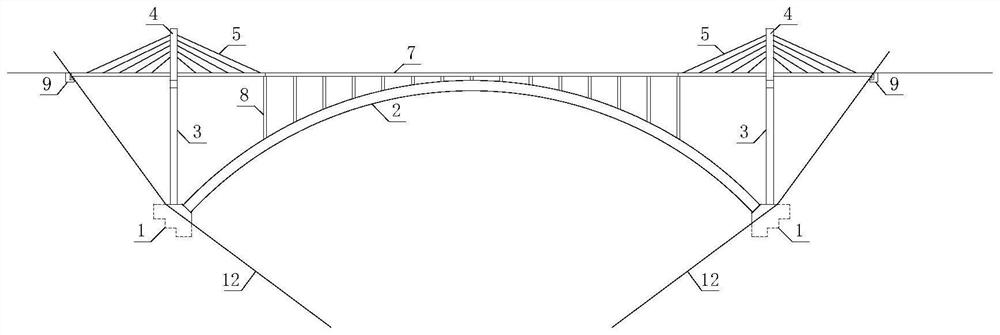
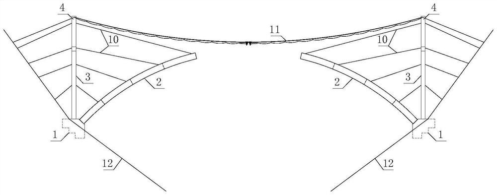
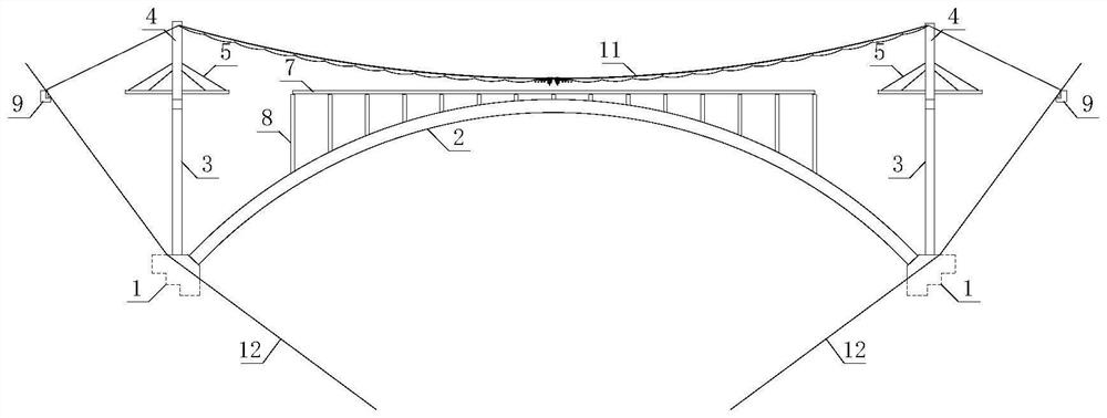
[0041] Such as Figure 1 to Figure 4 As shown in the figure, a construction method of an upward-supporting arch bridge structure in mountainous areas with a combination of permanent and adjacent areas. The technical idea is: the arch base is used as the common foundation of the permanent buckle tower and the arch bridge, and the permanent buckle tower is the bridge tower of the single-tower cable-stayed bridge after the bridge is completed. It can also be used as a temporary cable-stayed buckle and cable suspension system during the cantilever construction of the main arch ring. It is a "permanent combination" structure. On the building, and finally paved into a bridge. Specifically, the following construction steps are included:

[0042] 1. Anchor construction, combined with figure 2 As shown, the abutment 1 is set in the subgrade suitable for engineering geology below the ground line 12 through site survey, and the abutment 9 and abutment foundation are excavated and cast...

Embodiment 2

[0049] Such as figure 1 , figure 2 As shown, a mountainous upward-supporting arch bridge structure combining eternal and impermanence includes an abutment 1 and an abutment 9 as the foundation of the permanent buckle tower, and the lower tower column 3 of the permanent buckle tower is located on the abutment and connected to the top of the abutment 1 as a whole , the upper end of the lower tower column 3 of the permanent buckle tower is equipped with a permanent buckle tower beam 6 and the upper tower column 4 of the permanent buckle tower is installed on both sides of the permanent buckle tower beam 6; the main arch ring 2 is installed between the two abutments 1, and the main arch The upper end of the circle 2 is erected with the upper arch column 8; the bridge deck system is erected at the upper end of the abutment 9, the permanent buckle tower beam 6 and the upper end of the arch upper column 8.

[0050] Among them, the lower tower column 3 of the permanent buckle tower ...


PUM


Abstract

The invention provides a permanent and temporary combined mountainous area deck type arch bridge structure and a construction method thereof. The permanent and temporary combined mountainous area deck type arch bridge structure comprises an arch support and a bridge abutment which serve as a permanent buckling tower foundation, and a permanent buckling tower lower tower column is located on the arch support and connected with the arch support into a whole; a permanent buckling tower cross beam is mounted at the upper end of the permanent buckling tower lower tower column, and permanent buckling tower upper tower columns are mounted on the two sides of the permanent buckling tower cross beam; a main arch ring is installed between the two arch seats, and an on-arch stand column is erected at the upper end of the main arch ring; and a bridge deck system is erected at the upper ends of the bridge abutment, the permanent buckling tower cross beam and the on-arch stand column. The arch rib is rigidly connected with the permanent buckling tower through the skewback, the skewback serves as a common foundation of the permanent buckling tower and the arch bridge, and the construction measure cost of the arch bridge can be greatly reduced. The overarch high stand columns and approach bridge lower structures within the coverage range of the single-tower cable-stayed bridge are saved, the engineering scale is reduced, and meanwhile damage to mountains on the two sides is reduced.

Description

technical field [0001] The present invention relates to the technical field of civil engineering bridges, and more specifically relates to a construction method of a permanent-adjacent combined mountainous up-supported arch bridge structure. capacity and better economy. Background technique [0002] A bridge is a structure for crossing various obstacles (such as rivers or other structures) in highways, railways, urban roads, rural roads, and water conservancy construction. According to the mechanical characteristics of the structure, the bridge can be divided into beam, arch, rigid frame, suspension and composite system. The arch bridge is a classic bridge structure, which can be divided into upper, middle and lower-supported types according to the position of the bridge deck system. Due to its low building height, strong spanning ability, strong adaptability to mountainous terrain, and good economy, the overhead arch bridge has been widely used in areas where the bridge c...

Claims


Application Information

Patent Timeline
Patent Type & Authority Applications(China)
IPC IPC(8): E01D21/00E01D12/00
CPCE01D21/00E01D12/00Y02A30/60
Inventor 冯鹏程丁少凌聂尚杰刘琪王铖铖朱玉黄古剑宗昕王晓宁
Owner CCCC SECOND HIGHWAY CONSULTANTS CO LTD
Why Eureka
Try Eureka