Wet clutch friction plate surface groove profile line optimization method

A wet clutch and optimization method technology, applied in the field of vehicle clutch friction plates, can solve problems such as engine power consumption, thermal damage failure, reduction of hydraulic transmission system efficiency, etc. The effect of reducing displacement torque, rubbing frequency and axial rubbing force

Pending Publication Date: 2022-03-29
WUHAN UNIV OF SCI & TECH
View PDF0 Cites 2 Cited by
  • Summary
  • Abstract
  • Description
  • Claims
  • Application Information

AI Technical Summary

Problems solved by technology

The belt displacement torque will consume the power of the engine and reduce the efficiency of the hydraulic transmission system, and the rubbing phenomenon between the friction plate and the steel plate will continue to intensify as the clutch speed increases. At this time, the clutch not only consumes a large amount of engine power, but also faces Risk of failure due to thermal damage, jeopardizing the reliability of the vehicle drivetrain
With the introduction of high-speed drive motors in vehicle transmissions at the present stage and the continuous improvement of power density requirements for transmissions, the operating speed of wet clutches is also increasing, and the problem of clutch torque is becoming more and more prominent. However, there is currently no A specific technical solution that can effectively reduce the wide speed range of the no-load wet clutch with displacement torque

Method used


Image

  • Wet clutch friction plate surface groove profile line optimization method
  • Wet clutch friction plate surface groove profile line optimization method
  • Wet clutch friction plate surface groove profile line optimization method

Examples


Embodiment Construction

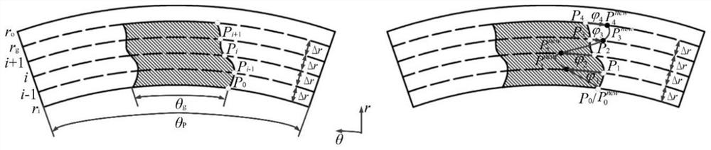
[0041] Below by embodiment, in conjunction with accompanying drawing, the technical scheme of the present invention is described further specifically, as figure 2 As shown in , it is a schematic diagram of parametric representation and optimization of any oil tank shape line by curve interpolation method (the shaded part is the tank area), where r g is the outer radius of the groove area on the surface of the friction plate, θ p (θ p =2π / N g ) is the circumferential angle corresponding to a periodic structure of the friction plate, θ g is the circumferential angle corresponding to the groove area, P i is the discrete point of the given oil groove shape line, the subscript i is the number of the discrete point, and the i-th discrete point P on the groove shape line i The coordinates in the cylindrical coordinate system are (r i ,θ i ), for the convenience of modeling, each discrete point P on the groove shape line of the oil tank i Distributed equidistantly along the ra...


PUM


Abstract

The invention provides a wet clutch friction plate surface groove profile line optimization method. The method comprises the following steps that 1, parametric modeling is conducted on a friction plate surface oil groove profile line; 2, selecting a design variable, determining a constraint condition, and constructing a wet clutch wide-speed low-belt-exhaust optimization design model based on an optimization target; and step 3, searching and optimizing through an optimization algorithm to obtain an optimal solution of design variable optimization. And the optimized wet clutch friction plate surface structure is obtained. According to the wet clutch obtained through the method, under the no-load working condition, the critical rotating speed of the friction pair gap rotating flow field for maintaining full oil film lubrication at the low-speed stage is obviously reduced, the rub-impact frequency of the friction pair at the high-speed stage is obviously reduced, and the wide-speed-range driven discharge torque of the no-load wet clutch is obviously reduced through the method.

Description

technical field [0001] The invention belongs to the technical field of vehicle clutch friction plates, and in particular relates to a method for optimizing the surface groove shape of a wet clutch friction plate. Background technique [0002] Wet clutches are the core components of vehicle hydraulic transmission systems, and are widely used in heavy-duty military vehicles, construction machinery transmissions, and passenger car automatic transmissions. When the wet clutch is in the no-load state and there is a speed difference between the friction plate and the steel plate, the viscous shearing action of the lubricating oil in the gap between the friction pair will inevitably produce a resistance torque on the friction plate / steel plate. In addition, when the clutch reaches a certain critical speed When , under the action of system disturbance and fluid force, the friction plate and the steel plate will collide and rub (hereinafter referred to as rubbing) to generate rubbing...

Claims


Application Information

Patent Timeline
Patent Type & Authority Applications(China)
IPC IPC(8): G06F30/15G06F30/17G06F30/27G06N3/04G06N3/12G06F111/04G06F111/06G06F111/08G06F111/10G06F119/14
CPCG06F30/15G06F30/17G06F30/27G06N3/04G06N3/126G06F2111/04G06F2111/06G06F2111/08G06F2111/10G06F2119/14Y02T10/40Y02T90/00
Inventor 张琳魏超严运兵许小伟邹俊逸蒙华唐学权
Owner WUHAN UNIV OF SCI & TECH
Why Eureka
Try Eureka