Platform conveying system, vehicle door conveying system and rail transit joint control conveying system

A technology of conveying system and rail transit

Pending Publication Date: 2022-04-01
CRRC TANGSHAN CO LTD +1
View PDF4 Cites 5 Cited by
  • Summary
  • Abstract
  • Description
  • Claims
  • Application Information

AI Technical Summary

Problems solved by technology

[0005] In the embodiment of this application, a rail transit joint control conveying system is provided to solve the problem that the existing logistics infrastructure is not matched, it is difficult to effectively connect, and it affects the construction of an integrated transportation system

Method used


Image

  • Platform conveying system, vehicle door conveying system and rail transit joint control conveying system
  • Platform conveying system, vehicle door conveying system and rail transit joint control conveying system
  • Platform conveying system, vehicle door conveying system and rail transit joint control conveying system

Examples


Embodiment 1

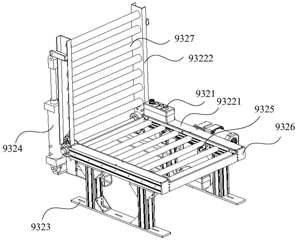
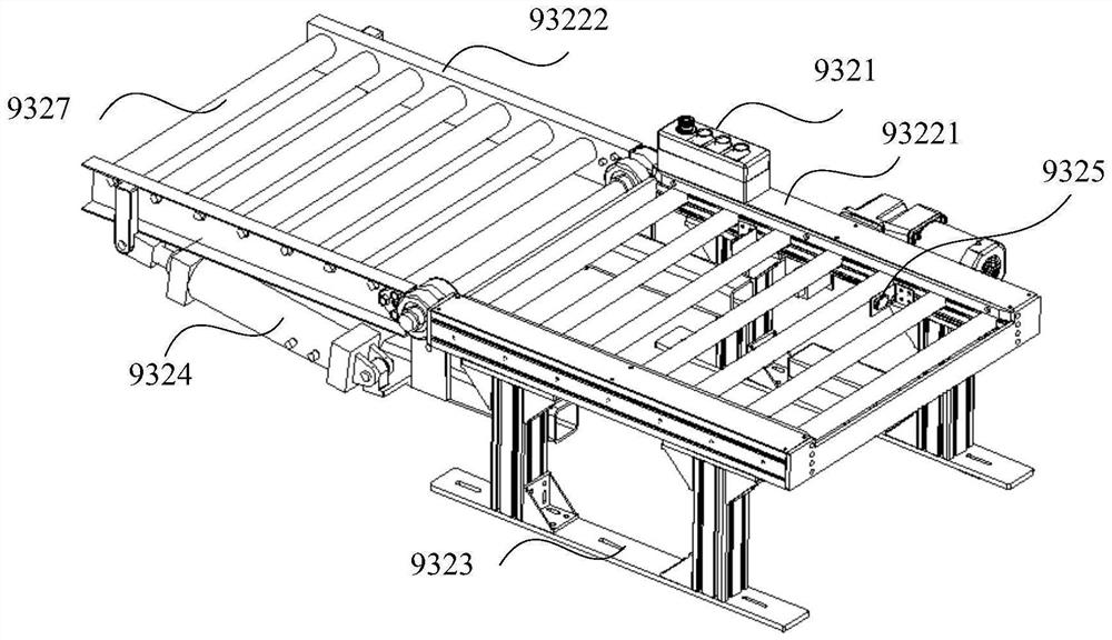
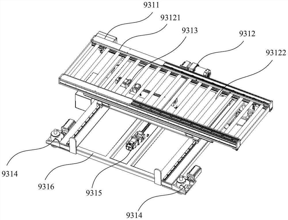
[0143]In one embodiment, the platform conveying system 931 includes a platform conveying device connected to the general control device, and the device includes a platform conveying component 9312 and a position adjustment component. Wherein, the platform conveying assembly 9312 is used for conveying goods, and one end of the platform conveying assembly 9312 is located on the platform, and the other end is used for docking with the conveying system 932 at the door; for example, it is set as a conveying belt, conveying chain or other conveying equipment. The position adjusting component is connected with the platform conveying component 9312, and the position adjusting component is used to drive the platform conveying component 9312 to adjust the spatial position; the master control device is respectively connected with the platform conveying component 9312 and the position adjusting component, which can be connected by wired or wireless communication. The device controls the ac...

Embodiment 2

[0175] Such as Figure 21 as shown, Figure 21 It is a schematic flowchart of a storage management method for rail vehicles provided in the embodiment of the present application. In a specific embodiment, the storage management method for rail vehicles provided by the application includes:

[0176] S941: Obtain the ULD information of the ULD to be put into storage;

[0177] Among them, ULD information generally includes ULD information including cargo on-station information, cargo arrival information, cargo attribution information and cargo characteristic information. Cargo attribution information such as the identity information of the belonging passenger, seat number and other information; cargo characteristic information such as storage conditions (such as storage temperature, humidity, etc.), cargo attributes, and other cargo identification information, etc. The acquisition method can be obtained by scanning the electronic label on the container through the code scannin...

Embodiment 3

[0249] see Figure 5-7 , Figure 5 A schematic diagram of the axonometric structure of a rail vehicle stacking system provided in the embodiment of the present application; Figure 6 for Figure 5 Schematic diagram of the main view structure; Figure 7 for Figure 5 Schematic diagram of the lateral structure.

[0250] The present application also provides a stacking system 91 , which includes a stacker frame 911 , a pallet fork 912 , a stacker driving device and a control device 913 . The stacker frame 911 is preferably a rectangular frame, and each edge of the rectangular frame can be detachably connected to facilitate production and processing. The pallet fork 912 is located on the stacker frame 911 and is used to pick and place the container. The stacker walking drive device is also located on the stacker frame 911, and is used to drive the stacker to walk in the rail vehicle. The stacker travel drive device can be a composition structure of a motor and a road wheel. ...


PUM


Abstract

According to the platform conveying system, the vehicle door conveying system and the rail transit joint control conveying system, the platform conveying system is arranged on a platform, the vehicle door conveying system is arranged on a rail vehicle, and a master control device is connected with the platform conveying system and the vehicle door conveying system so that the platform conveying system and the vehicle door conveying system can be in butt joint. Goods are conveyed on the platform and the rail vehicle, automatic conveying of the goods on the rail vehicle and the platform is achieved, meanwhile, reasonable labor division and effective connection can be conducted, the goods transfer efficiency is improved, and a foundation is laid for building of a comprehensive traffic transportation system. The position adjusting assembly drives the platform conveying assembly to conduct spatial position adjustment, so that the platform conveying assembly and the vehicle door conveying system can be in butt joint, the butt joint efficiency and the conveying efficiency are further improved, manual operation is reduced, intelligent development of the rail transit joint control conveying system is achieved, and the modern logistics development requirement is met.

Description

technical field [0001] The present application relates to the technical field of freight transport, in particular, to a platform transport system, a vehicle door transport system and a rail transit joint control transport system. Background technique [0002] With the advancement of science and technology, the Internet of Things has deeply penetrated into people's lives, and the rise of the e-commerce industry has stimulated the growth potential of the logistics industry. In just a few years, the business of express logistics has soared unprecedentedly, and the annual express business volume has grown rapidly at a rate of 20% to 30%. So how to better respond to the needs of express logistics has become our focus. While the scale is huge, what cannot be ignored is that the matching logistics infrastructure is relatively lagging behind compared with developed countries, and the proportion of modern facilities is low, which cannot meet the requirements of modern logistics devel...

Claims


Application Information

Patent Timeline
Patent Type & Authority Applications(China)
IPC IPC(8): B65G67/04
CPCB65G1/04B61D47/00B65G67/04
Inventor 刘晋林琳郭力杨国军刘鸿宇王艮川王俊立卢海超周强姚明刚
Owner CRRC TANGSHAN CO LTD
Why Eureka
Try Eureka