Eureka AIR delivers breakthrough ideas for toughest innovation challenges, trusted by R&D personnel around the world.

Floor system construction method for fabricated building and fabricated plane floor system

A construction method and prefabricated technology, which is applied in the processing of building materials, construction, building components, etc., can solve the problems of unevenness of the underside of the floor, inconvenience of construction at the bottom of the floor, and influence on construction efficiency, so as to improve construction efficiency , saving ceiling decoration, efficient construction

Active Publication Date: 2022-04-01
SHANDONG ONE STAR CO NSTRUCTION TECH CO LTD
View PDF6 Cites 0 Cited by
  • Summary
  • Abstract
  • Description
  • Claims
  • Application Information

AI Technical Summary

Problems solved by technology

Most of the construction of the existing floor is to lay the prefabricated main beam on the scaffold, and then lay the prefabricated secondary beam on the main beam. Suspended ceilings and other operations are required later to make up for it, which affects construction efficiency, and the construction process of the overall floor needs to use a lot of scaffolding for support, and the height difference at the bottom of the floor also brings great inconvenience to the construction

Method used


Image

  • Floor system construction method for fabricated building and fabricated plane floor system
  • Floor system construction method for fabricated building and fabricated plane floor system
  • Floor system construction method for fabricated building and fabricated plane floor system

Examples


Embodiment Construction

[0028] A floor construction method used in a prefabricated building according to the present invention, such as Figure 1-Figure 8 shown, including the following steps:

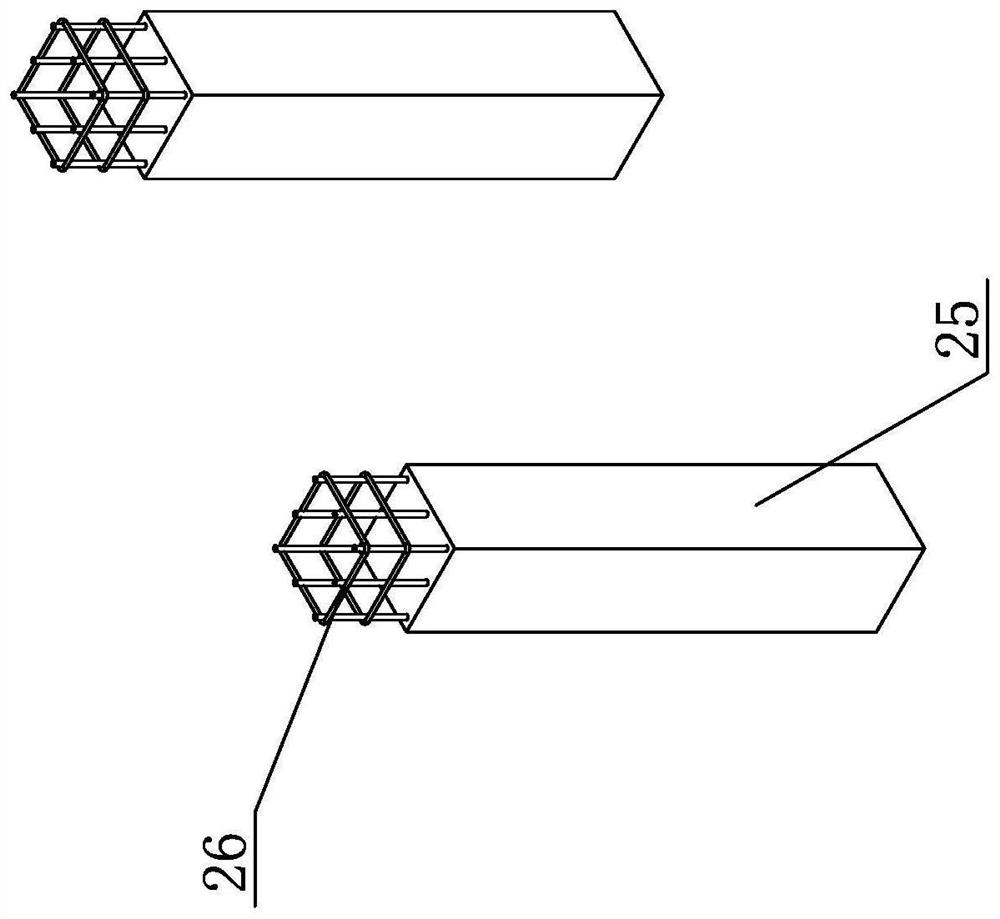
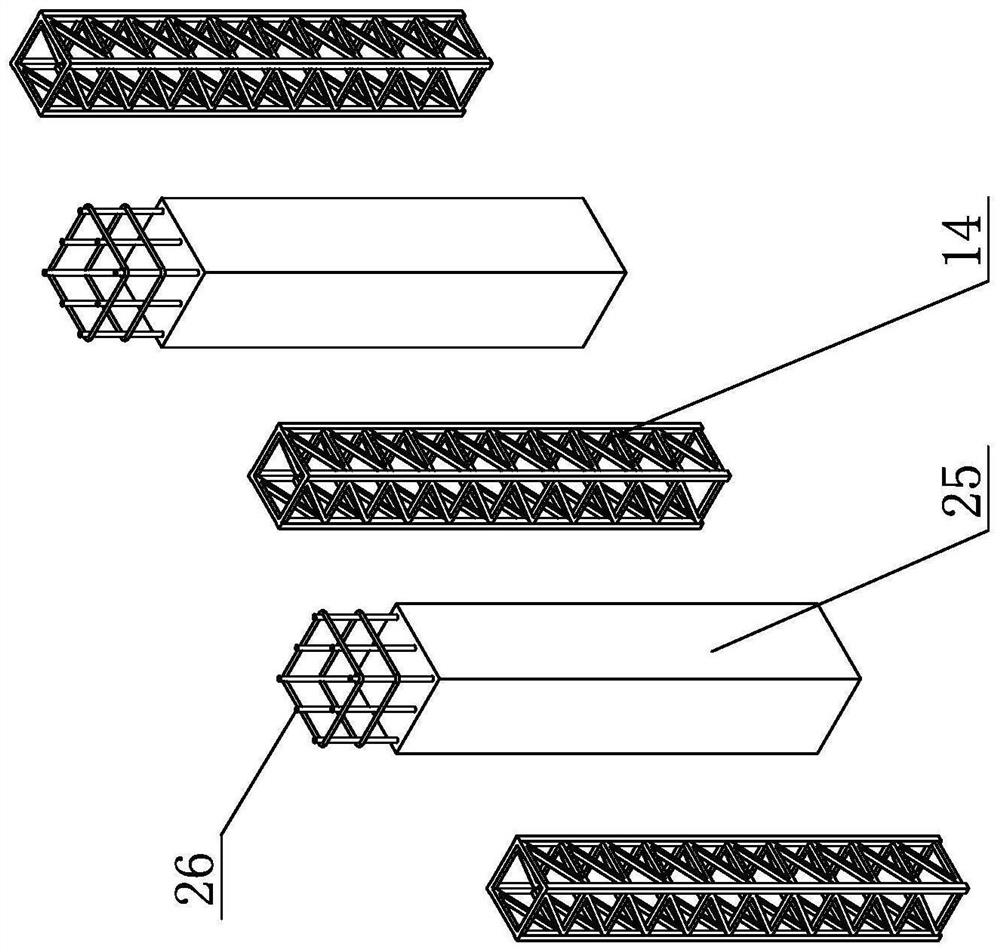
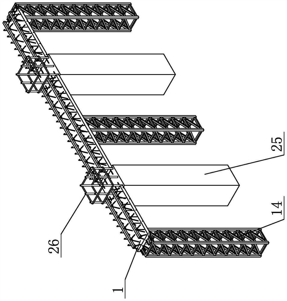
[0029] ① set column 25 at the position of the floor to be constructed;

[0030] ② After the setting of the column 25 is completed, the scaffolding 14 is built below the position of the longitudinal beam of the floor to be constructed;

[0031] ③ After the scaffolding 14 is built, the longitudinal beam truss plate 1 is placed between the adjacent columns 25 and on the scaffolding 14;

[0032] ④ After the longitudinal beam truss plate 1 is placed, the beam truss plate 2 is laid on the column 25, so that the beam truss plate 2 and the longitudinal beam truss plate 1 are vertically arranged, wherein both the longitudinal beam truss plate 1 and the beam truss plate 2 include The bottom plate 5 is provided with reinforcing bodies arranged along the length direction on the bottom plate 5, and several pre-embedded ...


PUM


Abstract

The floor system construction method for the fabricated building and the fabricated plane floor system have the positive effects that according to the floor system construction method for the fabricated building and the fabricated plane floor system, the longitudinal beam truss plates and the transverse beam truss plates are laid in advance, then concrete pouring is conducted, and the situation that the bottom of the floor system is not flush is avoided. Wherein the beam truss plates and the laminated slabs form a whole, the upper and lower surfaces of the floor can be ensured to be flush with each other, the longitudinal beam truss plates can also be used as supporting plates of the beam truss plates and the laminated slabs in the construction process, the number of supports of scaffolds can be effectively reduced, labor is saved, and the upper and lower surfaces of the floor are flush with each other, so that later ceiling decoration can be saved; the overall construction efficiency of the floor system is improved, the building floor height is reduced, the beams and the plates are all plates, and manufacturing and construction are efficient.

Description

technical field [0001] The invention relates to the technical field of floor construction, in particular to a floor construction method for an assembled building and an assembled flat floor. Background technique [0002] The floor is the floor structure in a multi-storey house. On the one hand, it bears various vertical loads and transmits them to the load-bearing walls; It bears horizontal loads and forms a space force structure for overall work. Most of the construction of the existing floor is to lay the prefabricated main beam on the scaffold, and then lay the prefabricated secondary beam on the main beam. Suspended ceilings and other operations are needed later to make up for it, which affects the construction efficiency, and the construction process of the overall floor needs to use a lot of scaffolding for support, and the height difference at the bottom of the floor also brings great inconvenience to the construction. Contents of the invention [0003] The purpos...

Claims


Application Information

Patent Timeline
Patent Type & Authority Applications(China)
IPC IPC(8): E04B5/17E04G21/00E04G21/02
CPCY02B30/00
Inventor 张树辉张波李明超王志辉刘赛阚大同
Owner SHANDONG ONE STAR CO NSTRUCTION TECH CO LTD
Why Eureka
Eureka Blog
Learn More