
Rotor disc of axial magnetic flux motor and forming method

A technology of axial magnetic flux and forming method, which is applied in the direction of magnetic circuit rotating parts, manufacturing stator/rotor body, magnetic circuit, etc., can solve the problem of inability to carry out industrialized mass production, failure to ensure the consistency of silicon steel blocks, and affect the efficiency of rotor forming and other issues to achieve the effect of ensuring dimensional consistency, improving production efficiency, and avoiding eddy current loss

Pending Publication Date: 2022-04-01
ZHEJIANG PANGOOD POWER TECH CO LTD
View PDF0 Cites 1 Cited by
  • Summary
  • Abstract
  • Description
  • Claims
  • Application Information

AI Technical Summary

Problems solved by technology

[0003] It can be seen from the above that each silicon steel block requires multiple sheets of different widths to be laminated, which not only has low production efficiency, but also cannot guarantee the consistency of each silicon steel block, and even causes eddy current loss, which reduces the reliability of the rotor.
In addition, the silicon steel block needs to be assembled with the rotor bracket one by one, which also affects the forming efficiency of the rotor, making it impossible to carry out industrialized mass production

Method used


Image

  • Rotor disc of axial magnetic flux motor and forming method
  • Rotor disc of axial magnetic flux motor and forming method
  • Rotor disc of axial magnetic flux motor and forming method

Examples


Embodiment Construction

[0032] The following description serves to disclose the present invention to enable those skilled in the art to carry out the present invention. The preferred embodiments described below are only examples, and those skilled in the art can devise other obvious variations. The basic principles of the present invention defined in the following description can be applied to other embodiments, variations, improvements, equivalents and other technical solutions without departing from the spirit and scope of the present invention.

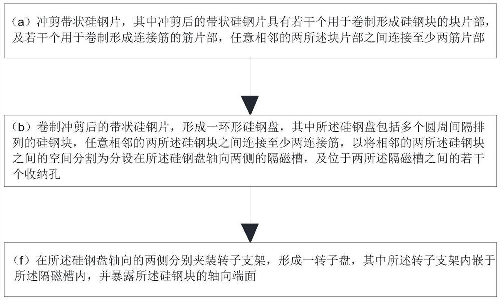
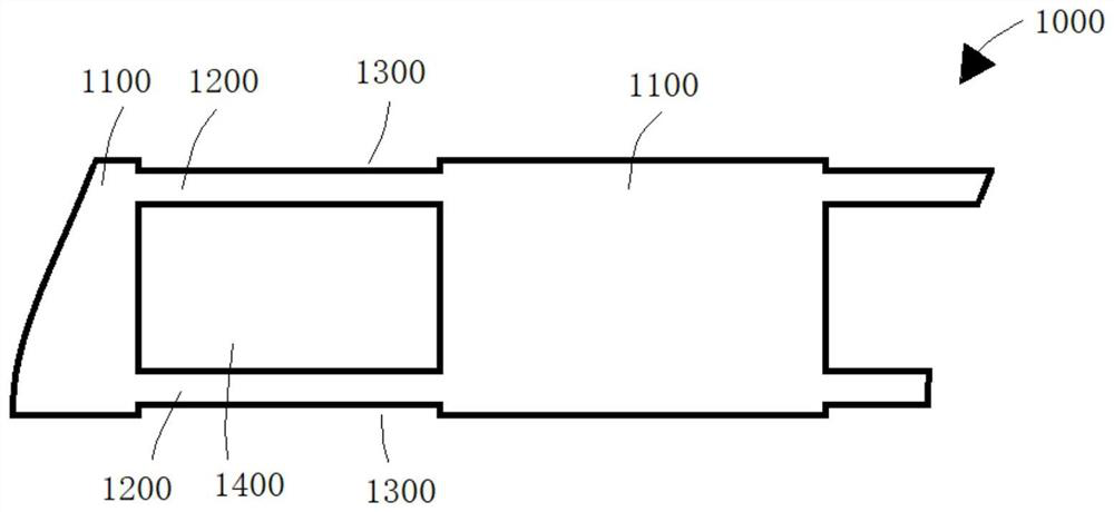
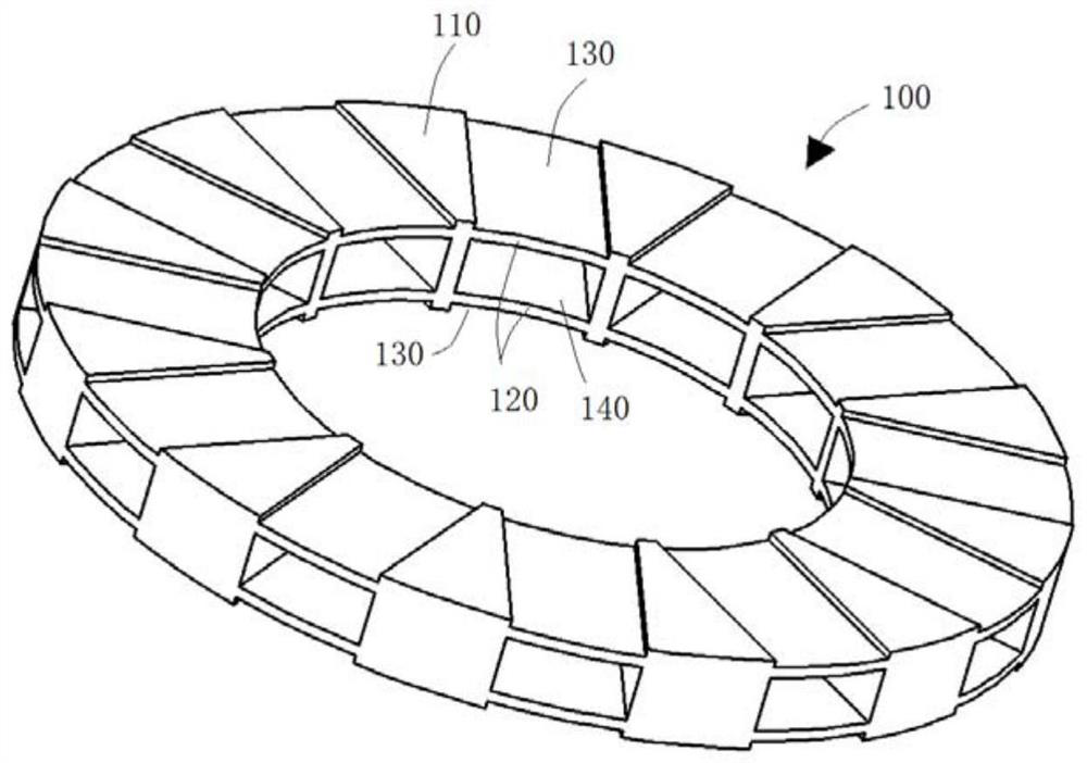
[0033] like Figure 1 to Figure 3 , Figure 5 As shown, the forming method of the rotor disk of the axial flux motor comprises the following steps:

[0034] (a) Punching and cutting strip-shaped silicon steel sheet 1000, wherein the strip-shaped silicon steel sheet 1000 after punching and shearing has several piece parts 1100 for forming silicon steel block 110 by rolling, and several pieces for forming connecting rib 120 by rolling The rib part 1200, ...


PUM


Abstract

The invention provides a rotor disc of an axial flux motor and a forming method, and the forming method comprises the steps: punching and shearing a strip-shaped silicon steel sheet which is provided with a plurality of block sheet parts used for rolling to form silicon steel blocks and a plurality of rib sheet parts used for rolling to form connecting ribs, at least two rib sheet parts are connected between any two adjacent sheet parts; the punched and sheared strip-shaped silicon steel sheet is rolled to form a silicon steel disc, the silicon steel disc comprises a plurality of silicon steel blocks arranged at intervals in the circumferential direction, and at least two connecting ribs are connected between any two adjacent silicon steel blocks so that the space between the two adjacent silicon steel blocks can be divided into magnetic isolation grooves formed in the two axial sides of the silicon steel disc; the plurality of accommodating holes are positioned between the two magnetic isolation grooves; the rotor supports are clamped on the two axial sides of the silicon steel disc respectively, the torque transmission rods are embedded into the containing holes, and the rotor disc is formed. The manufacturing efficiency and reliability of the silicon steel disc are improved, the consistency of the size, electromagnetism and the position of each silicon steel block on the rotor disc is ensured, and industrial batch production is further facilitated.

Description

technical field [0001] The invention relates to the field of axial flux motors, in particular to a rotor disc of an axial flux motor and a forming method. Background technique [0002] Axial flux motors are widely used in electric vehicles, general industries and household appliances due to their advantages of small axial size, high torque density, high power density and high efficiency. Existing axial flux motors generally use silicon steel sheets as the lamination material of the rotor and stator. During the forming process of the rotor, silicon steel sheets are stamped and cut to form multiple sheets of different widths, and then the multiple sheets are sequentially pressed according to The width is gradually increased to form a plurality of fan-shaped silicon steel blocks of the same shape, and finally the multiple silicon steel blocks are arranged on the rotor support in a circular interval, and the multi-layer sheets of each silicon steel block are along the rotor supp...

Claims


Application Information

Patent Timeline
Patent Type & Authority Applications(China)
IPC IPC(8): H02K15/03H02K1/276H02K1/30
Inventor 陈翾韩军于河波
Owner ZHEJIANG PANGOOD POWER TECH CO LTD
Learn More