
Method for detecting NR uplink control channel format 1

A technology of control channel format and detection method, which is applied in the directions of space transmit diversity, transmission system, energy consumption reduction, etc. It can solve the problem of large differences in signal-to-noise ratio conditions of multi-channel signals, no consideration of detection error minimization, loss of useful signals, etc. problem, to achieve the effect of overcoming the large difference in signal-to-noise ratio conditions

Active Publication Date: 2022-04-01
四川创智联恒科技有限公司
View PDF8 Cites 5 Cited by
  • Summary
  • Abstract
  • Description
  • Claims
  • Application Information

AI Technical Summary

Problems solved by technology

In a complex wireless propagation environment, the signal-to-noise ratio conditions of the above-mentioned multi-channel signals are quite different. In the existing technology, the multi-channel signals are directly averaged linearly, and there are obvious differences in the signal-to-noise ratio conditions of different RBs and different antennas. performance loss
[0003] Patent CN105873120A provides a scheme for screening different antenna signals through the SNR threshold, which can significantly improve the performance of distributed antenna scenarios, but loses too much usefulness in scenarios where the SNR conditions of different antennas are not much different. signal, with significant performance loss
Patent CN107453850A provides an interference scene enhancement scheme. First, measure the signal-to-noise ratio of different antenna signals, then calculate a weight coefficient between 0 and 1, and then perform weighted combination of different antenna signals, which can improve the system performance of the interference scene. However, this scheme does not consider the minimization of the final detection error, so there is still a significant performance loss

Method used


Image

  • Method for detecting NR uplink control channel format 1
  • Method for detecting NR uplink control channel format 1
  • Method for detecting NR uplink control channel format 1

Examples


Embodiment 1

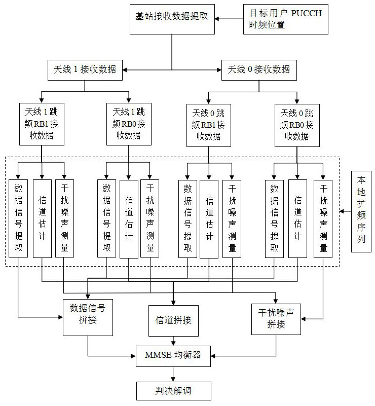
[0050] In this example, image 3 It is an implementation flowchart of Embodiment 1 of the present invention. In this embodiment, it is assumed that the number of receiving antennas of the base station is 2, and the PUCCH format 1 signal is transmitted by frequency hopping (2 frequency hopping RB positions). This embodiment mainly includes the following steps:

[0051] Step 1. Extraction of received data in the current time slot of the base station: the base station extracts the corresponding received signal according to the time-frequency resource position of the target user. The received signal includes 2 antennas, 2 frequency-hopping RB positions, and 12 subcarriers in each RB position7 data of time-domain symbols;

[0052] Step 2, split data from different antennas: split the signals received by the two antennas into two signals, that is, the data received by antenna 0 and the signal received by antenna 1, each signal contains two frequency-hopping RB positions, and each RB ...


PUM


Abstract

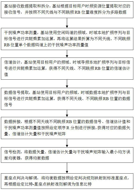
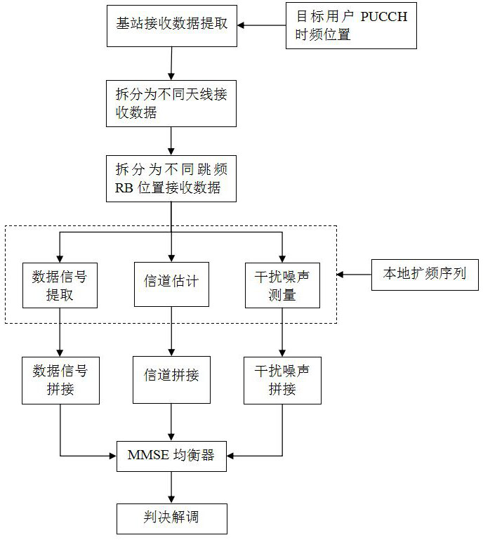
The invention discloses a method for detecting an NR uplink control channel format 1, which comprises the following steps of: receiving data by a base station, extracting and splitting the data, and calculating a target signal by using a frequency domain local spread spectrum sequence and a time domain local spread spectrum sequence of an idle code channel to obtain an interference noise power measurement value, a channel estimation value and a data signal; splicing operation data of different antennas at different frequency hopping RB positions according to a given sequence R to obtain a corresponding data vector, a channel estimation vector and an interference noise matrix; inputting the data vector, the channel estimation vector and the interference noise matrix into a minimum mean square error equalizer to obtain equalized data; and mapping the balanced data to a standard constellation point according to a given decision rule, and demodulating the balanced data into an information bit according to a given bit-constellation point mapping criterion. According to the invention, different antenna signals at different frequency hopping RB positions are spliced and then sent to the MMSE equalizer at one time, so that the performance loss caused by large signal-to-noise ratio condition difference among multiple paths of signals can be effectively overcome.

Description

technical field [0001] The present invention relates to the field of mobile communication, in particular to a detection method for NR uplink control channel format 1. Background technique [0002] In the NR (new air interface, the fifth generation mobile communication technology) system, the base station uses multiple antennas and different RB (frequency domain resource block, 1RB contains 12 OFDM subcarriers) positions to receive the PUCCH (Physical Uplink Control Channel) format 1 signal. In a complex wireless propagation environment, the signal-to-noise ratio conditions of the above-mentioned multi-channel signals are quite different. In the existing technology, the multi-channel signals are directly averaged linearly, and there are obvious differences in the signal-to-noise ratio conditions of different RBs and different antennas. performance loss. [0003] Patent CN105873120A provides a scheme for screening different antenna signals through the SNR threshold, which ca...

Claims


Application Information

Patent Timeline
IPC IPC(8): H04B7/08H04L5/00H04L25/02H04B1/7136
CPCY02D30/70
Inventor 吕磊陈英
Owner 四川创智联恒科技有限公司
Learn More