Electrical switching system

A technology of electric switch and protection switch, which is applied in the field of electric switch system, and can solve the problems that can no longer be spaced apart, damaged parts, etc.

Pending Publication Date: 2022-04-01
ELLENBERGER & POENSGEN GMBH
View PDF11 Cites 0 Cited by
  • Summary
  • Abstract
  • Description
  • Claims
  • Application Information

AI Technical Summary

Problems solved by technology

But because the two are partially liquefied on the surface, the contact and counter-contact fuse, so the two can no longer be spaced apart after cooling
If the fault persists now, the current continues to be directed through the protective switch, which can lead to damage to the components protected by the protective switch
The protective switch is also no longer usable, since an accidental interruption of the current flow is no longer possible due to the fusion of the contacts and counter contacts.

Method used


Image

  • Electrical switching system
  • Electrical switching system
  • Electrical switching system

Examples


Embodiment Construction

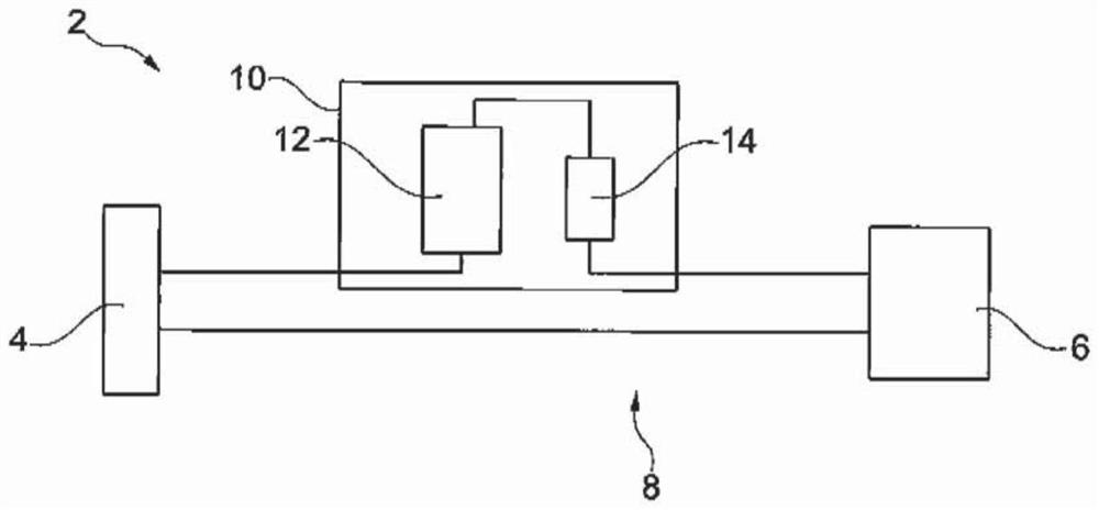
[0035] exist figure 1 A schematic diagram of an industrial plant 2 is illustrated in . The industrial plant 2 has a power source 4 and an actuator 6 operated therewith. The AC voltage of 50 Hz or 60 Hz is provided by the power supply 4 . The voltage is in particular 277V or 480V. Actuator 6 comprises, for example, an electric motor or a press and is electrically coupled to power source 4 via line 8 such that actuator 6 is powered via line 8 .

[0036] Furthermore, the industrial system 2 includes a power switch 10 which, in one embodiment, is a component of the line 8 and is arranged in a switch cabinet (not shown). Alternatively, the power switch 10 is arranged on the power source 4 or on the actuator 6 . The power switch 10 has a protection switch 12 and an overcurrent protection mechanism 14 connected in series therewith. The electrical series is introduced into one of the cores of the line 8 .

[0037] In this example, the rated current of the power switch 10 is 60 A...


PUM


Abstract

The invention relates to an electrical switching system (24), in particular a protection switch (12), comprising: a first current rail (34) extending in a longitudinal direction (26), carrying a first contact (36) and a second contact (38) spaced apart from the first contact (36) in the longitudinal direction (26), and having a first current connection (42); and a second current rail (20) extending in the longitudinal direction (26), the second current rail (20) carrying a first counter contact (28) and a second counter contact (30) spaced apart from the first counter contact (28) in the longitudinal direction (26), and the second current rail (20) having a second current connection (32). The second current rail (20) is mounted perpendicular to the longitudinal direction (26) so as to be movable in the transverse direction (22), and the first current rail (34) partially overlaps the second current rail (20) in the longitudinal direction (26). In the longitudinal direction (26), the contact (36, 38) and the counter contact (28, 30) are arranged between the two current connections (32, 42) in the overlapping region (40). The invention further relates to a protection switch (12).

Description

technical field [0001] The invention relates to an electrical switching system having a first current rail and a second current rail. The invention also relates to a protective switch having such an electrical switching system. Background technique [0002] Protective switches usually have an electrical switching system. Electrical switching systems are usually designed mechanically so that electrical separation is also possible. In this case, the electrical switching system generally has a contact and a counter contact mounted movably relative thereto. In particular, the contact and the counter-contact are each attached to a current rail, wherein the support is usually carried by the current rail. If the protective switch is in the closed state, ie a current can be conducted via the protective switch, the contact part bears against the corresponding contact part, so that there is a direct mechanical connection between the two. Current flows through the contact and the c...

Claims


Application Information

Patent Timeline
Patent Type & Authority Applications(China)
IPC IPC(8): H01H1/54
CPCH01H1/54H01H50/54H01H71/082
Inventor 胡贝特·哈雷尔亨德里克-克里斯蒂安·科普夫克劳斯·鲁斯克劳斯·维尔纳于尔根·泽贝尔
Owner ELLENBERGER & POENSGEN GMBH
Why Eureka
Try Eureka