Intelligent logistics storage real-time monitoring display equipment

A technology for real-time monitoring and display equipment, applied in the direction of instruments, identification devices, etc., can solve the problems of light radiation affecting observers, unfavorable observers viewing a single display screen, etc., to reduce the time required for opening and closing, and reduce service life. , the effect of reducing light radiation

Active Publication Date: 2022-04-05
无锡星智数服科技有限公司
View PDF14 Cites 0 Cited by
  • Summary
  • Abstract
  • Description
  • Claims
  • Application Information

AI Technical Summary

Problems solved by technology

[0004] There are still some deficiencies in the existing real-time monitoring and display equipment for smart logistics warehousing. Due to the large storage space, more monitoring needs to be set up, so that there are more real-time display screens, and these monitoring screens do not require observers to stare at them al

Method used


Image

  • Intelligent logistics storage real-time monitoring display equipment
  • Intelligent logistics storage real-time monitoring display equipment
  • Intelligent logistics storage real-time monitoring display equipment

Examples


Embodiment 1

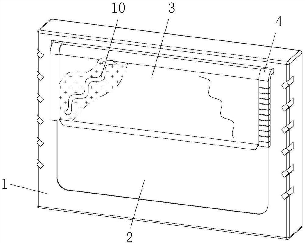
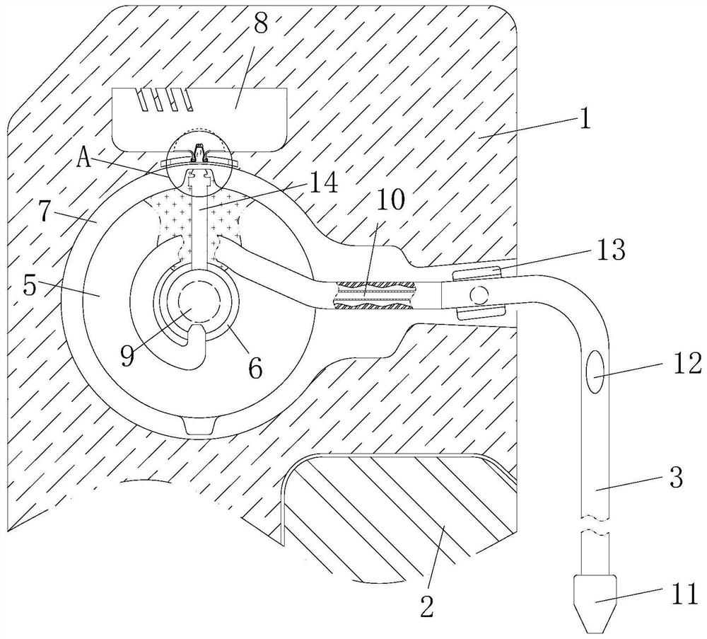
[0028] Such as Figure 1 to Figure 2As shown, a smart logistics warehouse real-time monitoring and display device described in the embodiment of the present invention includes a connecting frame 1, a receiving display module 2 is fixedly installed on the front end of the connecting frame 1, and a front end of the connecting frame 1 is provided with a Storage groove 7, the inner side of described storage groove 7 is fixedly installed with servomotor 9, and the transmission end of described servomotor 9 is fixedly installed with center wheel 6, and the two ends of described center wheel 6 are fixedly installed with take-up reel 5, so The outer side of the center wheel 6 is fixedly equipped with a blocking curtain 3, and the end of the blocking curtain 3 away from the center wheel 6 is fixedly equipped with a counterweight 11. During work, the receiving display module 2 receives the data transmitted by monitoring and setting, and The data is displayed to the outside to complete t...

Embodiment 2

[0038] Such as Figure 4 As shown in Comparative Example 1, another embodiment of the present invention is: the middle part of the barrier curtain 3 is provided with several groups of parallel flow grooves 22, and the inner side of the flow groove 22 is fixedly installed with a closing curtain. 23. The edge of the closure curtain 23 is made of elastic material, and the length of the closure curtain 23 is greater than the vertical length of the flow groove 22. The bottom end of the closure curtain 23 is located on one side of the blocking curtain 3. When working, it cooperates with the flow groove 22 and the closing curtain 23 are set so that during the upward movement of the blocking curtain 3, the flow groove 22 can smoothly circulate gas, thereby reducing air resistance, thereby assisting the upward process of the blocking curtain 3, and when the blocking curtain 3 descends , in conjunction with the length setting of the closing curtain 23, the blocking curtain 3 will slowly...


PUM


Abstract

The invention belongs to the field of monitoring display, and particularly relates to intelligent logistics storage real-time monitoring display equipment which comprises a connecting frame, a receiving display module is fixedly mounted at the front end of the connecting frame, and a storage groove is formed in the position, close to the top end, of the front end of the connecting frame. The blocking curtain is located on the outer side of the receiving display module and blocks and isolates displayed pictures and light, when one-by-one observation is needed, the servo motor is started to drive the center wheel to rotate, and the blocking curtain can be rolled and displayed by the receiving display module. Compared with the prior art, the optical radiation of the multiple groups of receiving display modules to observers is greatly reduced, so that the working environment in the monitoring room is improved, the observers can observe the single receiving display module conveniently, the receiving display modules do not need to be switched on and off frequently, and the problem that the service life is shortened due to frequent switching on and off is solved.

Description

technical field [0001] The invention belongs to the field of monitoring and display, in particular to a real-time monitoring and display device for intelligent logistics storage. Background technique [0002] With the development of science and technology, mechanical monitoring settings have gradually replaced manual guards, and the mechanical monitoring settings also have the function of recording, which can be retrieved and viewed at any time. In the storage environment, due to the large area of ​​the environment that needs to be guarded, it is necessary to use mechanical monitoring. Add monitoring and display equipment. [0003] A Chinese patent with the publication number CN1300418C discloses a monitoring and display device used on construction machinery to display a screen image of a dead-end surveillance camera on the monitoring display as a perspective view in the background of the superimposed instrument data screen image. The Gauge Data screen image indicates the r...

Claims


Application Information

Patent Timeline
IPC IPC(8): B65H75/44G09F9/00
Inventor 蔡子祥吴娓娓谢锡阳钱文彬
Owner 无锡星智数服科技有限公司
Why Eureka
Try Eureka